Eureka AIR delivers breakthrough ideas for toughest innovation challenges, trusted by R&D personnel around the world.

Electro-optical modulator having high extinction ratio when functioning as switch

Inactive Publication Date: 2014-10-30
HON HAI PRECISION IND CO LTD
View PDF44 Cites 4 Cited by
  • Summary
  • Abstract
  • Description
  • Claims
  • Application Information

AI Technical Summary

Benefits of technology

The present patent relates to an improved electro-optic modulator that can function as a switch with a high extinction ratio. The technical effect of the patent is to provide an electro-optic modulator that can overcome the problem of limited extinction ratio when used as a switch, resulting in a lower output in the off state and a higher output in the on state.

Problems solved by technology

As a result, the lightwaves traversing the first branch have a phase shift and thus interfere with lightwaves traversing another branch of the Y-shaped waveguide (hereinafter the second branch).
However, being limited by manufacturing imprecision, all the properties of the lightwaves traversing the first and second branches are not the same.
An extinction ratio of the switch is thus less than satisfactory.

Method used


Image

  • Electro-optical modulator having high extinction ratio when functioning as switch
  • Electro-optical modulator having high extinction ratio when functioning as switch
  • Electro-optical modulator having high extinction ratio when functioning as switch

Examples


Embodiment Construction

[0009]Embodiments of the present disclosure will be described with reference to the drawings.

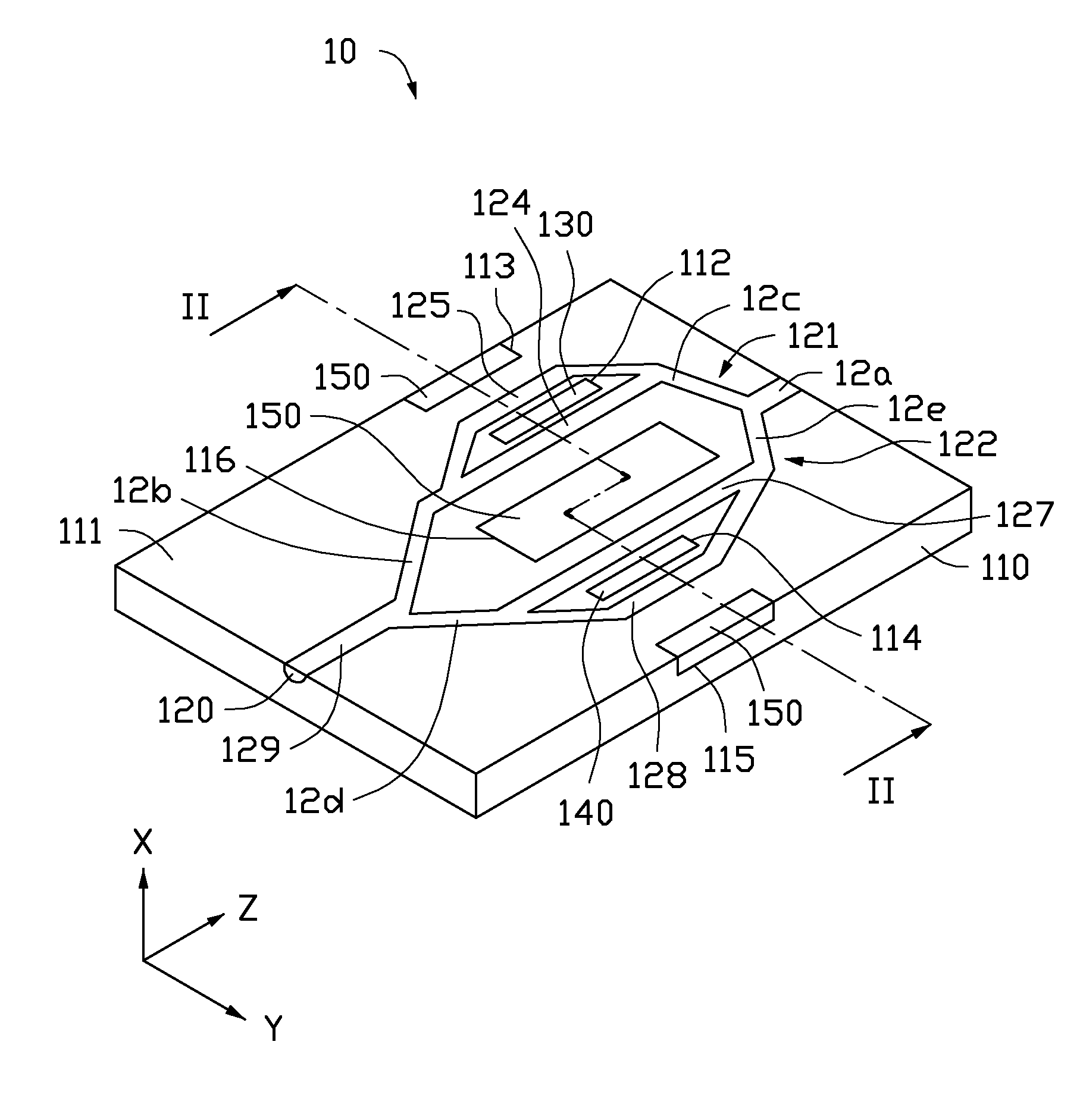
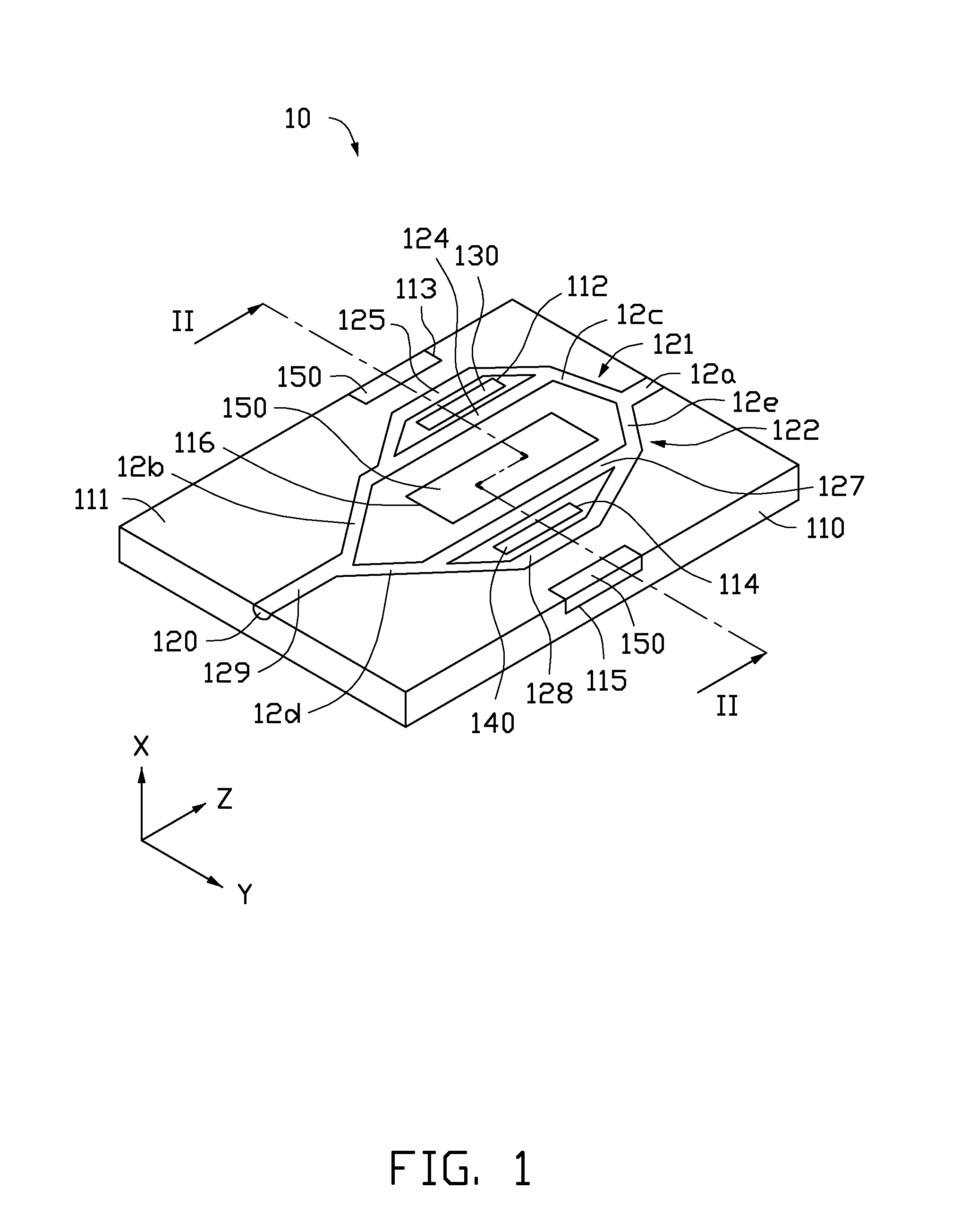
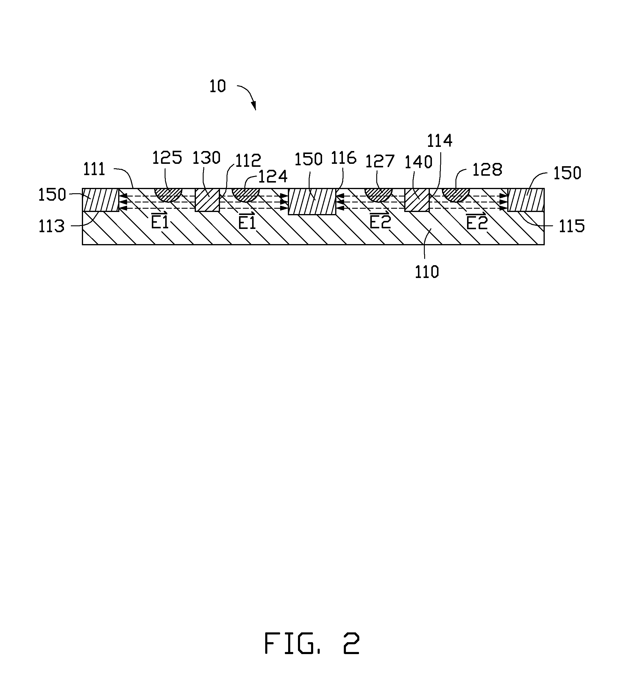
[0010]FIGS. 1 and 2 show an electro-optic modulator 10, according to an embodiment. The modulator 10 includes a substrate 110, a waveguide 120, a first modulating electrode 130, a second modulating electrode 140, and three ground electrodes 150.

[0011]The substrate 110 is made of lithium niobate (LiNbO3) crystal to increase a bandwidth of the modulator 10, as LiNbO3 crystal has a high response speed. In this embodiment, the substrate 110 is substantially rectangular and includes a top surface 111.

[0012]The waveguide 120 is formed by applying a layer of titanium as a coating on a shape corresponding to the waveguide 120 and diffusing the titanium into the substrate 110 by, for example, a high temperature diffusion technology. In this embodiment, the waveguide 120 is formed in the top surface 111.

[0013]The waveguide 120 is Y-shaped and formed in the substrate 110. The waveguide 120 includes a f...


PUM


Abstract

An electro-optic modulator includes a substrate, an end-to-end Y-shaped waveguide for optical divergence and convergence, and electrodes. The waveguide is formed in the substrate and the electrodes are formed in the substrate and received voltages act to modulate first and second sections of the waveguide such that the optical output by the first and second sections are equal or opposite to each other in all necessary respects regarding phase and amplitude.

Description

BACKGROUND[0001]1. Technical Field[0002]The present disclosure relates to integrated optics and, particularly, to an electro-optic modulator having a high extinction ratio when functioning as a switch.[0003]2. Description of Related Art[0004]Electro-optic modulators, such as Mach-Zehner electro-optic modulators, change a refractive index of a branch of a Y-shaped waveguide (hereinafter the first branch) using a modulating electric field, utilizing electro-optic effect. Thus, the modulator can alter a phase of lightwaves traversing the first branch. As a result, the lightwaves traversing the first branch have a phase shift and thus interfere with lightwaves traversing another branch of the Y-shaped waveguide (hereinafter the second branch). An output of the Y-shaped waveguide is modulated as the output depends on the phase shift, which in turn depends on the modulating electric field. However, being limited by manufacturing imprecision, all the properties of the lightwaves traversing...

Claims


Application Information

Patent Timeline
IPC IPC(8): G02F1/225
CPCG02F1/2257G02F1/225G02F2201/12
Inventor HUANG, HSIN-SHUN
Owner HON HAI PRECISION IND CO LTD
Why Eureka
Eureka Blog
Learn More