Sole for a shoe

Active Publication Date: 2014-11-06
ADIDAS
View PDF54 Cites 62 Cited by
  • Summary
  • Abstract
  • Description
  • Claims
  • Application Information

AI Technical Summary

Benefits of technology

[0019]Each of the plurality of first outsole elements may have an associated flexible region of the outsole, which facilitates movement of each of the pl

Problems solved by technology

However, a disadvantage of this construction is, in particular, that the cushioning pad extends in a planar and roughly evenly thick manner throughout the entire sole and therefore influences the properties of the sole across the entire sole area in the same manner, without a possibility to selectively control the cushioning- and stability characteristics.
This can, in particular, result in the sole not having the desired stability in the midfoot area.
This construction is, however, tech

Method used


Image

  • Sole for a shoe
  • Sole for a shoe
  • Sole for a shoe

Examples


embodiment 100

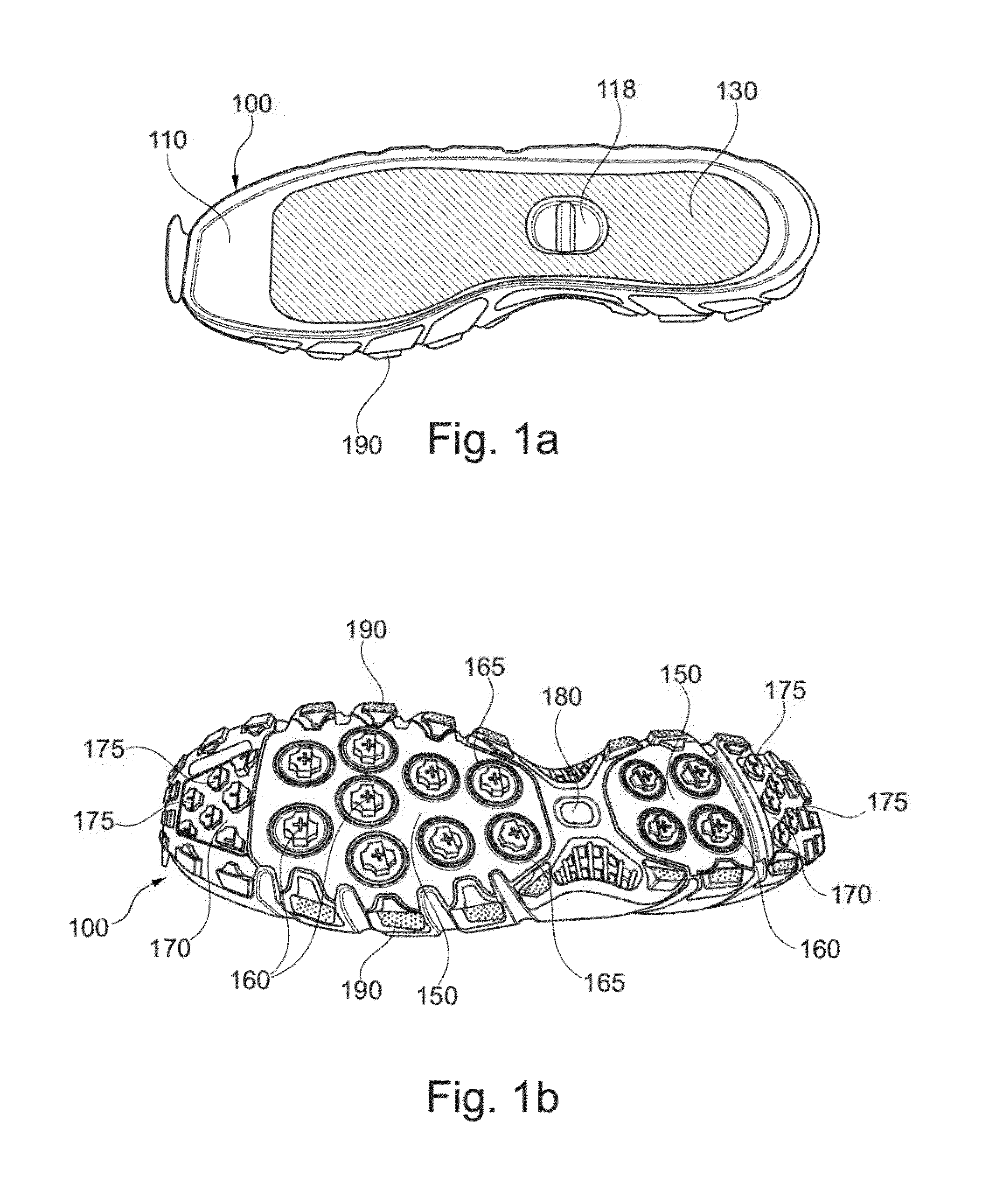
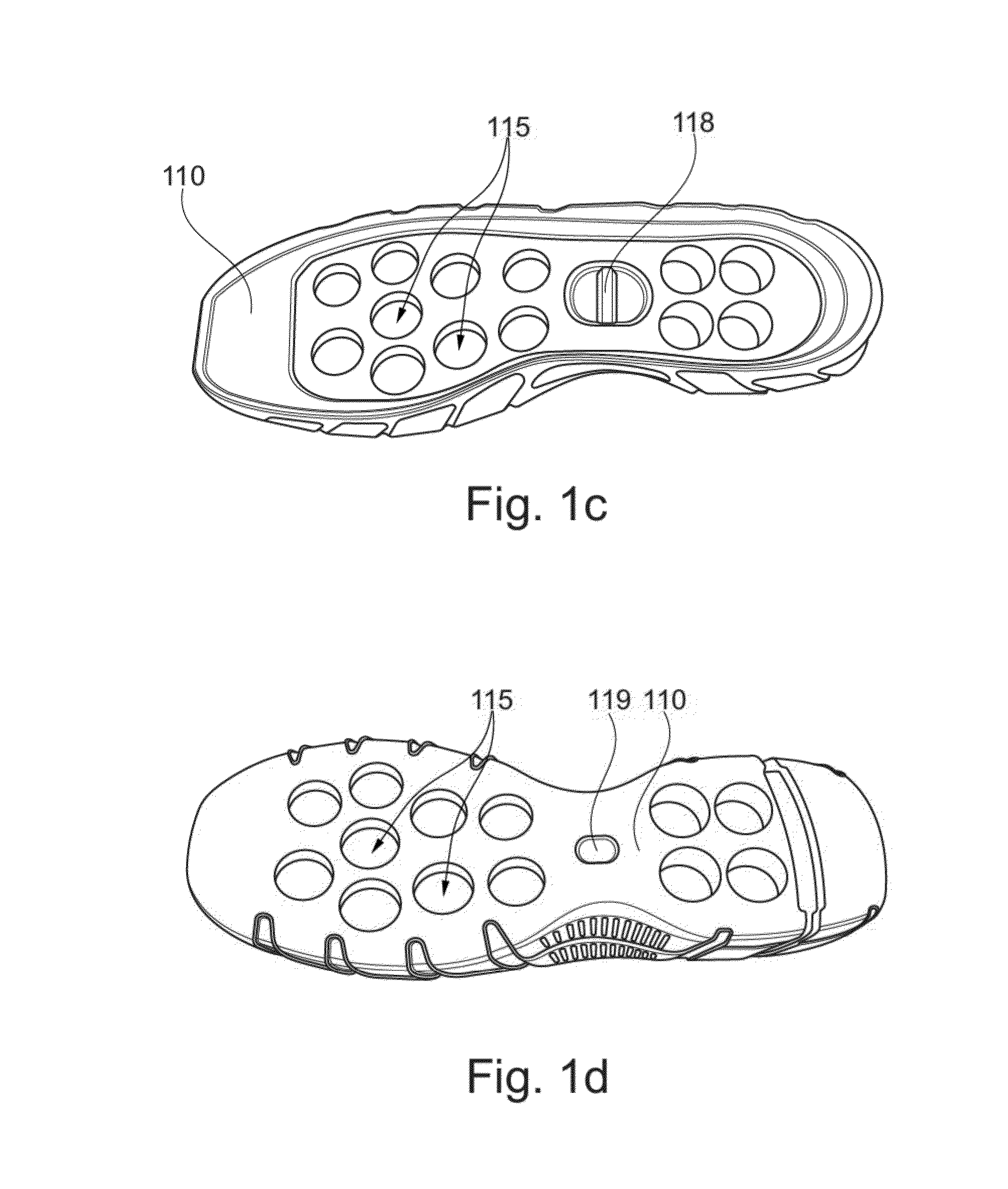
[0079]In certain embodiments, the base body 110 in the embodiment 100 are integrally formed. In other embodiments, the base body 110 may be formed of multiple parts. Furthermore, within the scope of this document, at least two are to be regarded as a plurality. For example, a plurality of deformation elements 120 respectively comprise at least two deformation elements 120 in the forefoot region and in the hindfoot region, or 9 deformation elements in the forefoot region and 4 deformation elements in the hindfoot region, or 10 deformation elements in the forefoot region and 4 deformation elements in the hindfoot region, or any suitable combinations of deformation elements 120 in any suitable region.

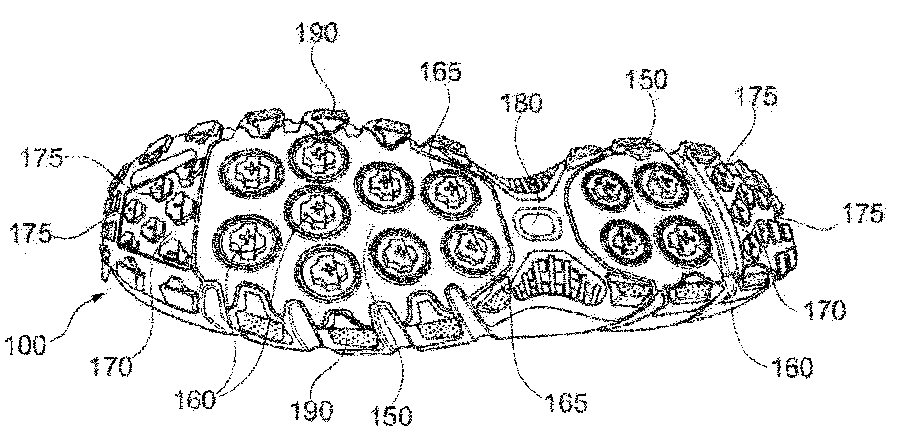
[0080]The sole 100 further comprises an outsole, which comprises a first outsole region 150 and a plurality of first outsole elements 160, which may be formed downward protruding and may be integrally formed with the first outsole region 150. The outsole is arranged in such a way at the mi...

embodiment 300

[0109]In the embodiment 300 shown here, the first outsole region 350 and the first outsole elements 360 are furthermore formed at least partially transparent. In the finished sole 300, the deformation elements 320 and the base body 310 are thus at least partially visible from outside, as indicated in FIG. 3b. Different colorings of the base body 310 and the deformation elements 320 visualize the functionality.

[0110]FIGS. 4 and 5 show further embodiments of inventive soles 400, 500.

[0111]The sole 400 in particular comprises an outsole made from rubber and formed as a single integral piece. The outsole comprises a first outsole region 450 and a second outsole region 470. The outsole further comprises a plurality of first downward protruding outsole elements 460 which each have an associated flexible region 465, as already described several times. Moreover, the second outsole region 470 comprises a plurality of downward protruding profile elements 475 which serve a further profiling of...

embodiment 800

[0122]FIGS. 8a-c show a further embodiment 800 of an inventive sole. The sole 800 comprises a midsole comprising a base body 810 and two deformation elements 820. In some embodiments, the base body 810 comprises ethylene-vinyl-acetate (EVA) of a greater stiffness, whereas the two deformation elements 820 comprise EVA of a lower stiffness. Here, the base body 810 and the deformation elements 820 may be manufactured jointly, in particular integrally in one piece, for example by two-component injection molding. In other embodiments, the base body 810 and the deformation elements 820 are manufactured through a die cutting process and then joined together. Alternatively, the deformation elements 820 comprise a particle foam, in particular a particle foam from expanded thermoplastic urethane or expanded polypropylene. The harder base body 810 is in this case may be arranged around the rim of the sole 800 and in the midfoot region and provides the sole 800 with the required stability.

[0123...


PUM


Abstract

Described are soles for a shoe having a midsole with a base body and a plurality of deformation elements, and an outsole with a first outsole region and a plurality of first outsole elements. Pressure load on one first outsole element of the plurality of first outsole elements leads to a deformation of at least one of the plurality of deformation elements which are associated with the one first outsole element of the plurality of first outsole elements.

Description

CROSS REFERENCE TO RELATED APPLICATION[0001]This application is related to and claims priority benefits from German Patent Application No. DE 10 2013 208 170.7, filed on May 3, 2013, entitled SOLE FOR A SHOE (“the '170 application”). The '170 application is hereby incorporated herein in its entirety by this reference.FIELD OF THE INVENTION[0002]The present invention relates to a sole for a shoe, in particular a sole for a sports shoe.BACKGROUND[0003]With the aid of shoe soles, shoes are provided with a wealth of different characteristics that may be pronounced in various strengths depending on the specific type of shoe. Primarily, the shoe soles have a protective function. They protect the foot of the respective wearer by way of their increased stiffness in comparison with the shoe shaft from injuries through e.g. sharp objects on which the shoe wearer treads. Furthermore, the outsole typically protects the midsole of the shoe from excessive wear by an increased abrasion resistance....

Claims


Application Information

Patent Timeline
IPC IPC(8): A43B13/18
CPCA43B13/18A43B13/125A43B13/14A43B13/184A43B13/26
Inventor PRICE, DANIEL STEPHENWARDLAW, ANGUSHOLMES, CHRISTOPHER EDWARDBRUNS, FALKLEIMER, ROBERTWHITEMAN, JOHNROBINSON, TIMOTHY KELVINSCHLARB, HEIKOFREEMAN, WARREN
Owner ADIDAS
Why Eureka
Try Eureka