Compression Latch

a compression latch and latch technology, applied in the field of compression latches, can solve the problems of increasing the amount of lateral force that must be applied, difficulty in adjusting the latch, and damage to the closure surround, so as to reduce the lateral movement of the striker

Inactive Publication Date: 2014-11-13
WESTON BODY HARDWARE
View PDF1 Cites 6 Cited by
  • Summary
  • Abstract
  • Description
  • Claims
  • Application Information

AI Technical Summary

Benefits of technology

[0009]The latch is configured such that in use, lateral movement of the striker with respect to the housing is minimised as the latch member nears the closed position.
[0010]The striker being pivotable in relation to the latch arm allows the arc of the striker to be varied as the latch member moves between an open position and the closed position. The arc of the striker as the latch member reaches the closed position can thus advantageously be adjusted to reduce lateral movement of the striker with respect to a closure surround, yet the striker can be moved out of the way of the closure surround when in the open position, so it does not interfere with closure.

Problems solved by technology

There can be difficulties with existing compression latches of this type.
The latch member must clear the closure surround when the latch is in a fully open position, so that it does not prevent the closure from being fully opened.
The latch member can move across the surface of the closure surround as it reaches the closed position, causing damage to the closure surround and increasing the amount of lateral force that must be applied to move the latch member to the closed position.
However, decreasing the length of the latch member is not always possible, as the latch member must reach the closure surround.
In addition, decreasing the length of the latch member can lead to the latch being positioned closer to the closure surround to ensure that the latch member reaches the closure surround, and so increases the likelihood of the latch member interfering with the closure surround when the latch is in a fully open position.

Method used


Image

  • Compression Latch
  • Compression Latch
  • Compression Latch

Examples


Embodiment Construction

)

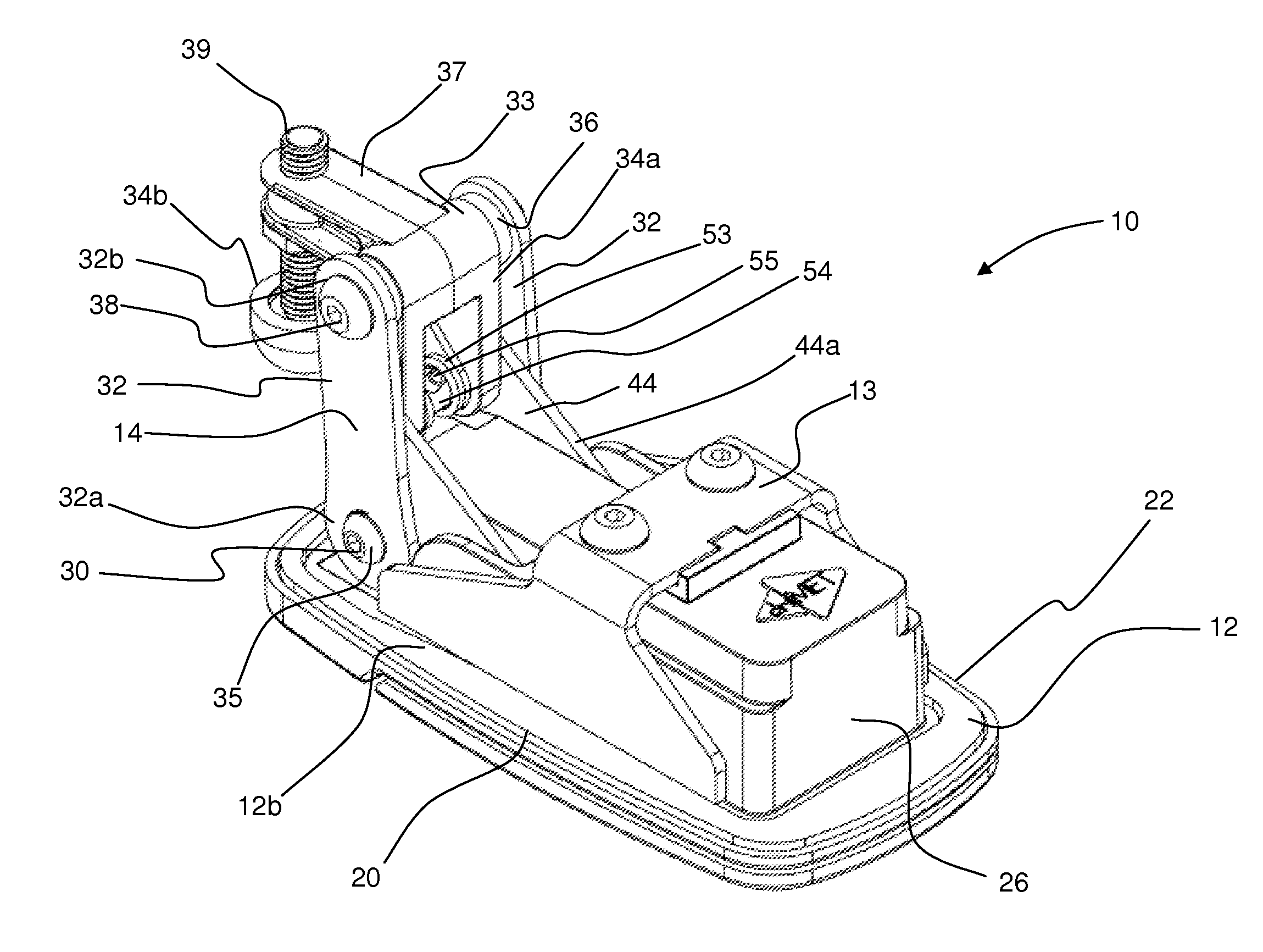
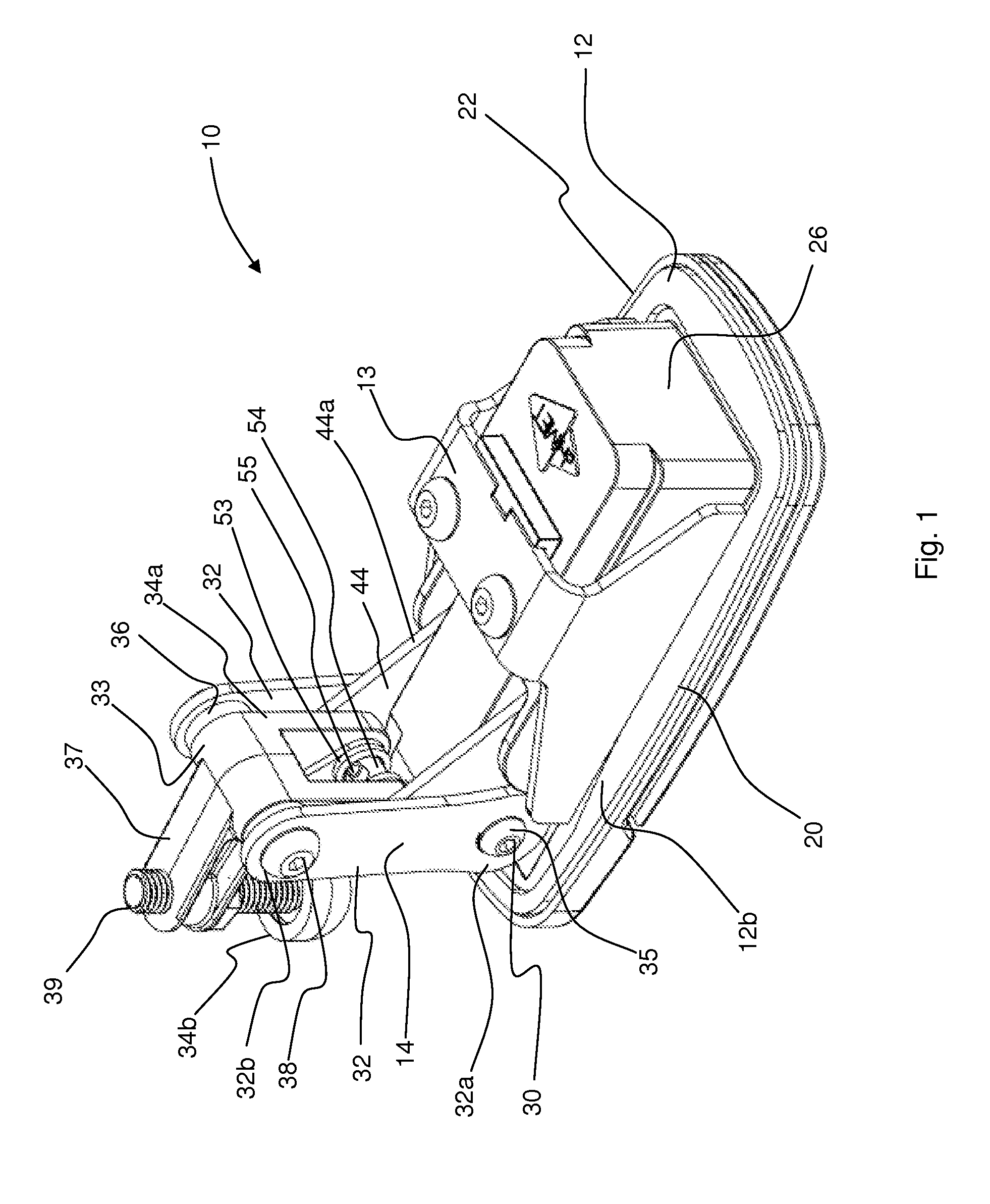
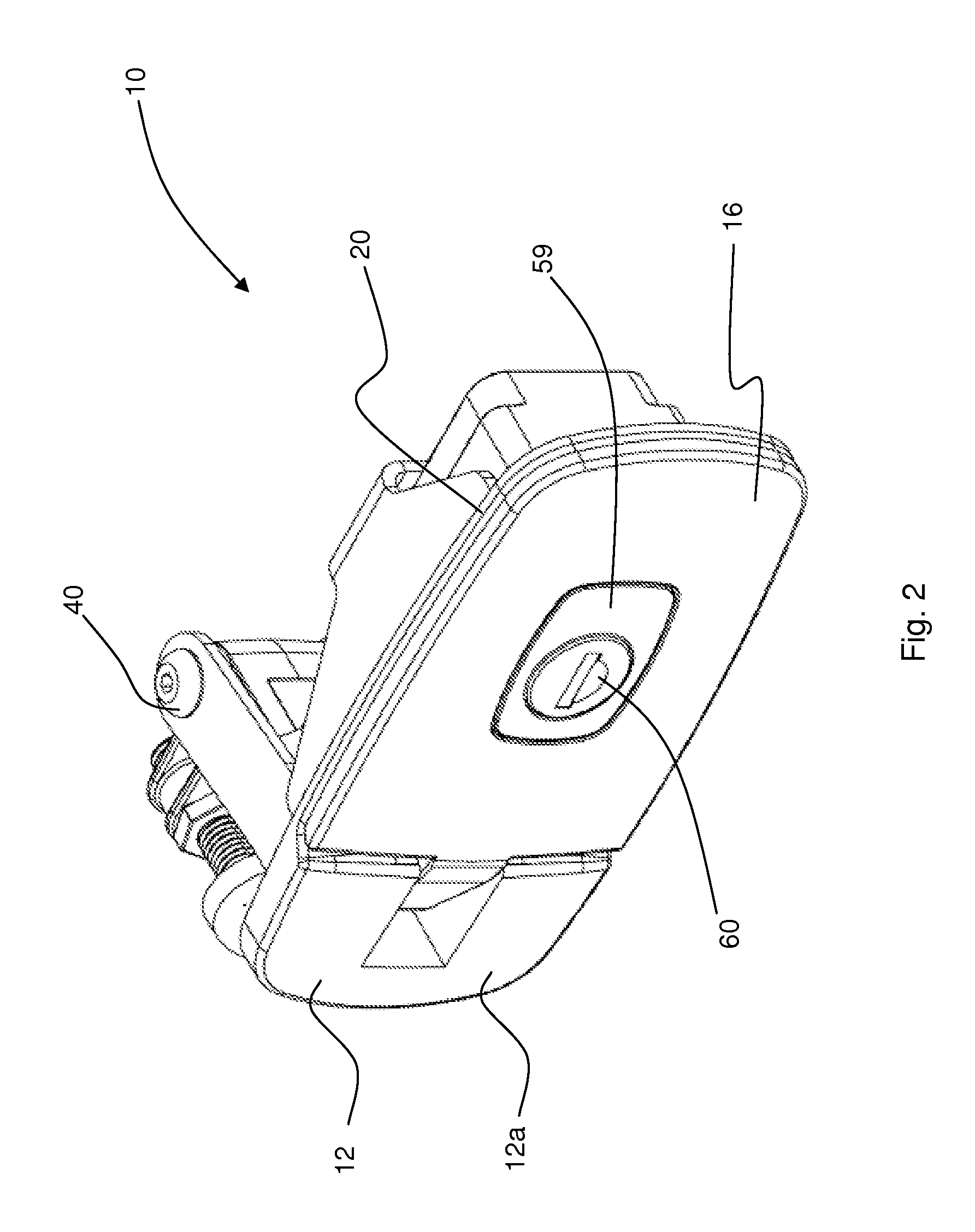
[0034]Referring to FIGS. 1 to 5, a trigger compression latch according to an embodiment of the present invention is generally indicated at 10. The latch 10 has a housing 12, a latch member 14 and a handle 16 configured to operate the latch member 14. The latch 10 is movable between a closed position, as shown in FIGS. 1 and 2, in which the latch member 14 is actuated to apply pressure to a closure surround 18 (see FIGS. 3 to 5), and a fully open position, wherein the latch member 14 is clear of the closure surround.

[0035]The housing 12 defines an outboard side 12a and an inboard side 12b, and has a main body 20 defining a plane. The housing 12 has a first edge 22 intended to be mounted proximal a free edge of a closure 24 (i.e. the edge over which the latch member 14 extends). The housing 12 comprises a seal (not shown) at the edge 22, allowing the housing 12 to be sealed against the closure 24. In addition, the inboard side 12b is substantially sealed from the outboard side 12a to...


PUM


Abstract

A compression latch for a closure, the latch including a housing, a latch member and an input shaft configured to drive the latch. The latch member is pivotably connected to the housing at a latch member pivot point. The latch member includes a latch arm and a striker. The latch arm first end is connected to the input shaft at the latch member pivot point, such that the latch member is pivotable about the latch member pivot point between an open position and a closed position upon operation of the input shaft. The striker is pivotably connected to the latch arm second end at a first striker pivot point. The latch arm is configured to move the striker with respect to the housing in a first arc and the linkage is configured to pivot the striker with respect to the housing about the latch arm in a second arc.

Description

CROSS-REFERENCE TO RELATED APPLICATIONS[0001]This application claims priority to Great Britain Application No. GB1308273.0 filed on May 8, 2013, the entire contents of which are hereby incorporated by reference herein.TECHNICAL FIELD[0002]The present invention relates to a compression latch for a closure.BACKGROUND OF THE INVENTION[0003]It is known to use compression latches in a variety of applications, for example when force is required to hold a closure in place, or when sealing of a closure (e.g. a door, window or access panel of a vehicle or an item of construction plant) is needed. Compression latches are often of the type known as a “trigger” latch, having a trigger latch member in the handle that is used to retain the handle in a closed position.[0004]Such latches often incorporate a pivotable latch member held against a closure surround by a latch mechanism. The latch member is configured to be pivoted to a closed position by a handle. The latch mechanism holds the latch me...

Claims


Application Information

Patent Timeline
Patent Type & Authority Applications(United States)
IPC IPC(8): E05C17/00
CPCE05C17/00E05C3/006E05C3/08E05C5/00E05B5/00E05B17/0025Y10T292/1083
Inventor WOLLACOTT, MARTINLESLIE, MICHAEL
Owner WESTON BODY HARDWARE
Why Eureka
Try Eureka