Projection display apparatus
a technology of projection display and display screen, which is applied in the direction of color television details, television systems, pulse techniques, etc., can solve the problems of image quality degradation, and achieve the effect of keeping video quality and reducing the frequency of changing the optical path
- Summary
- Abstract
- Description
- Claims
- Application Information
AI Technical Summary
Benefits of technology
Problems solved by technology
Method used
Image

Examples
first embodiment
[0038]1.Configuration of the Projection display apparatus
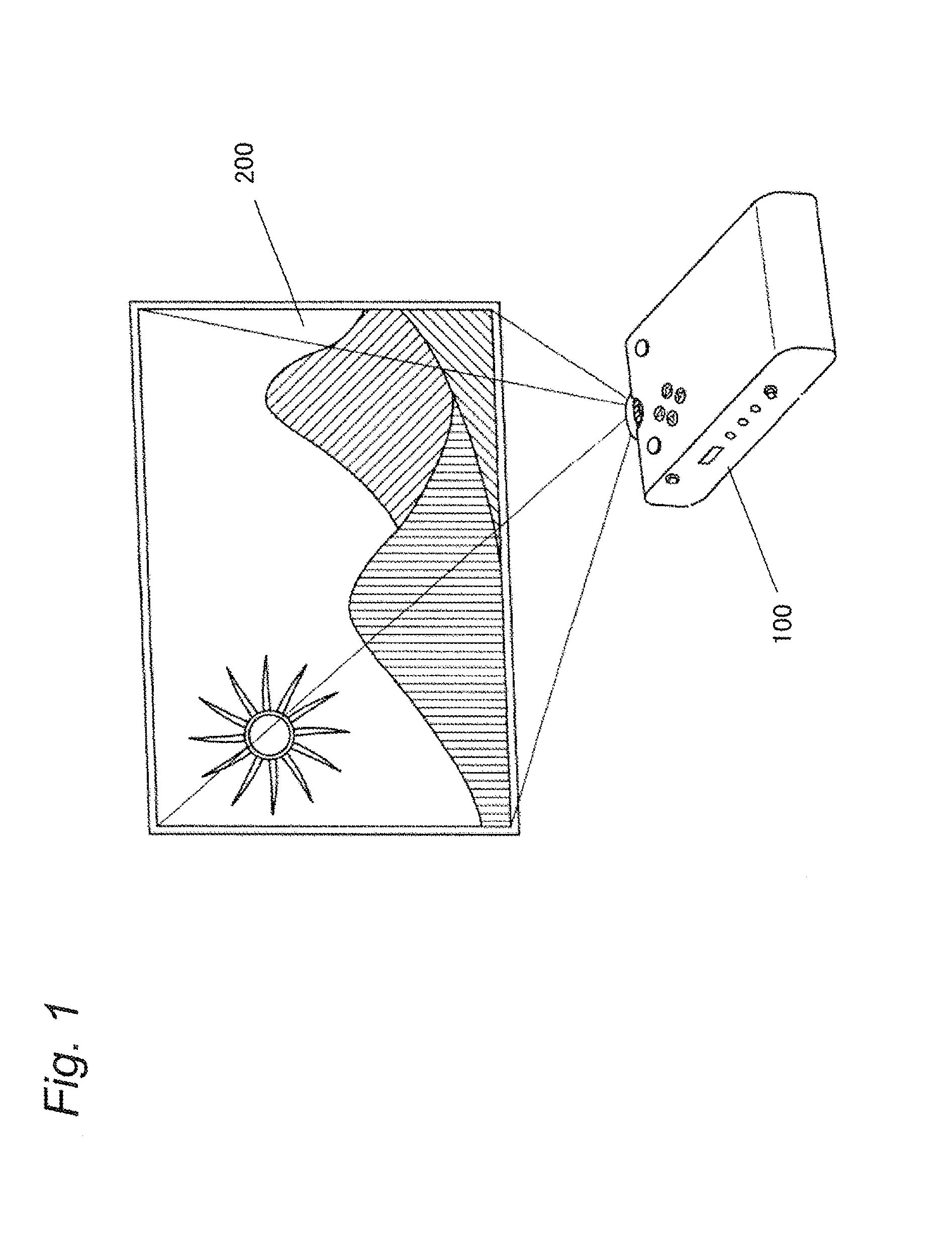
[0039]A configuration of the projection display apparatus will be described with reference to FIGS. 1 and 2. FIG. 1 is an external perspective view of a projection display apparatus 100. As illustrated in FIG. 1, the projection display apparatus 100 projects an image light generated in accordance with a video input signal onto a screen (projection plane) 200.
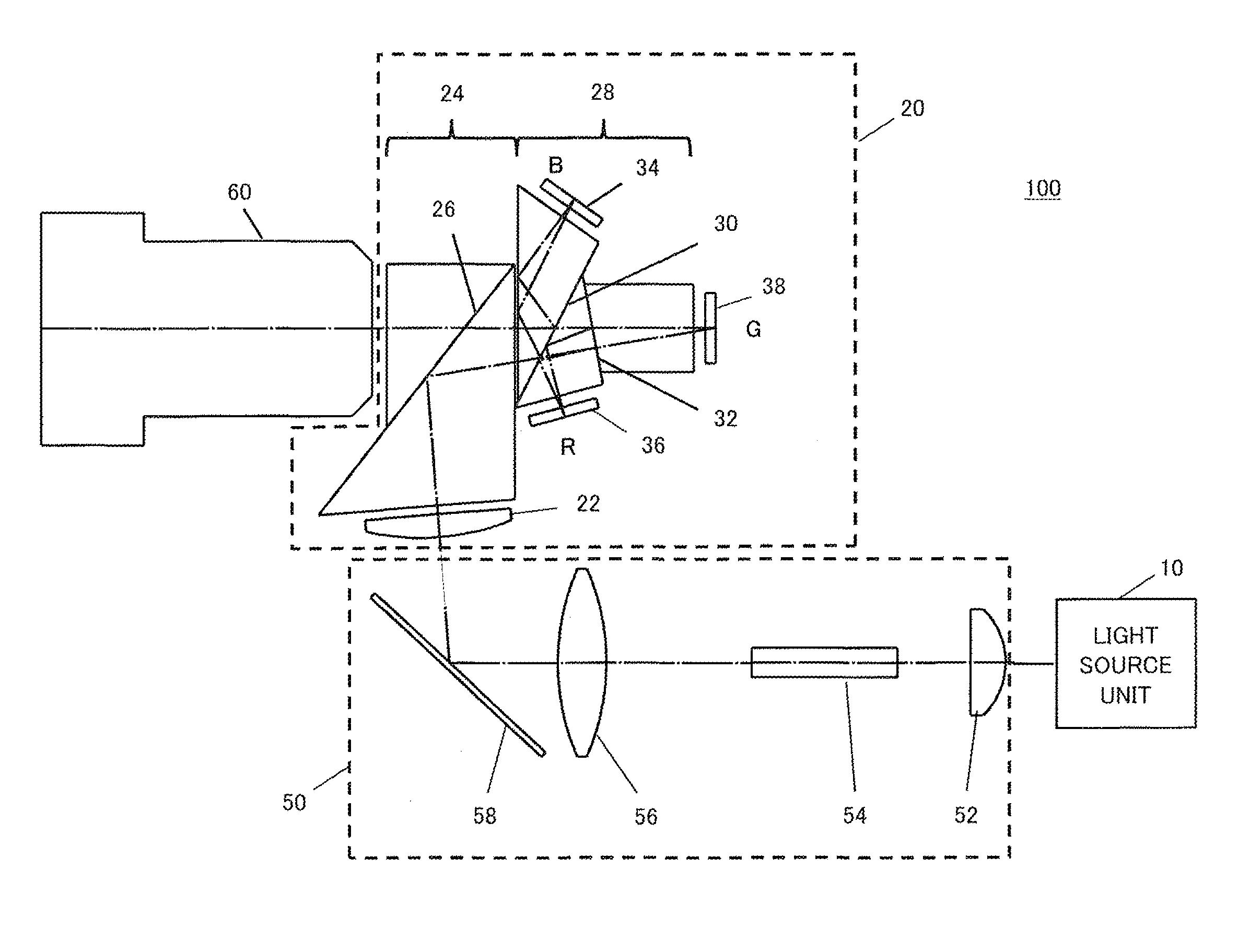
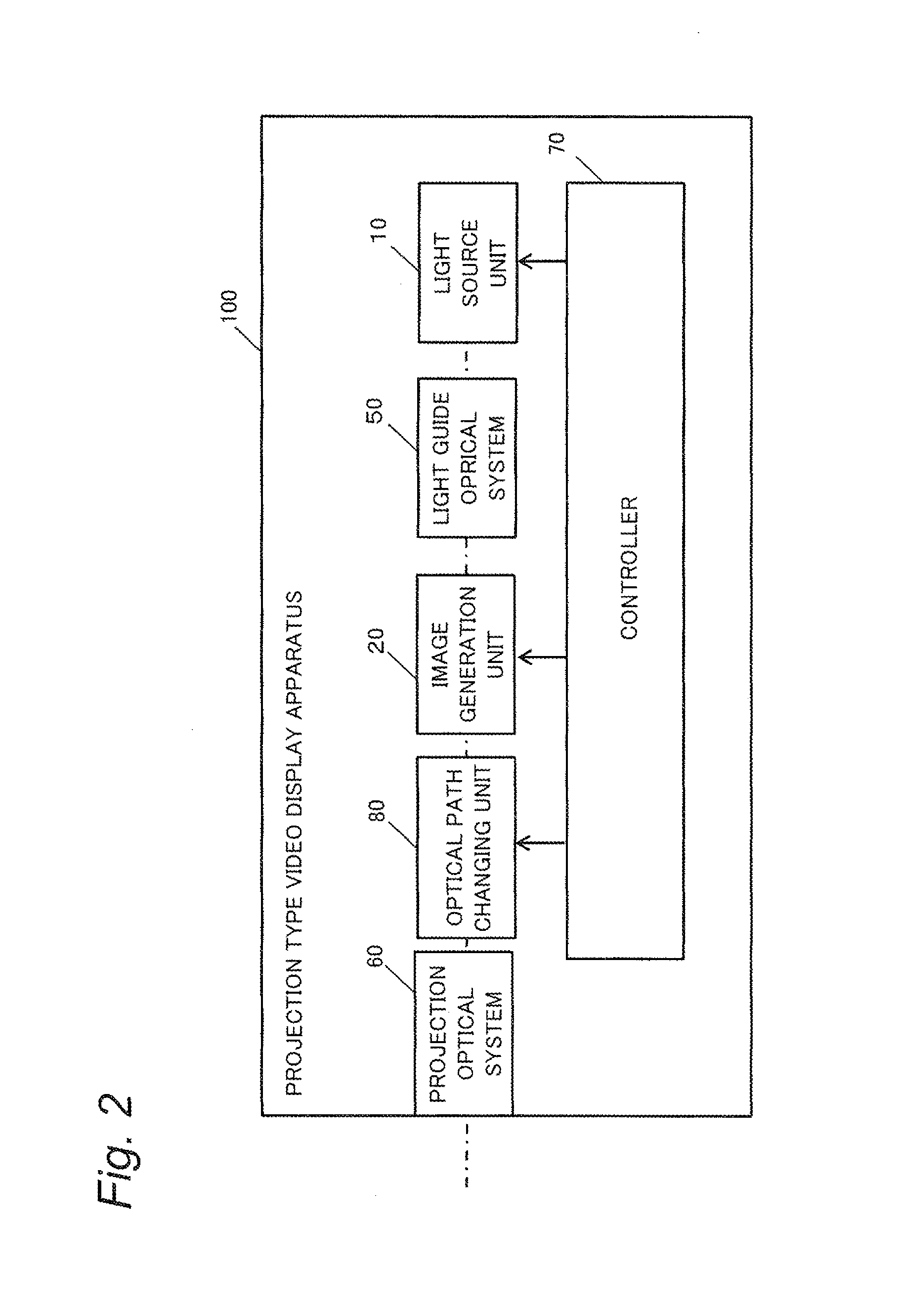
[0040]FIG. 2 is a block diagram illustrating a configuration of the projection display apparatus 100. The projection display apparatus 100 includes a light source unit 10, an image generation unit 20 which generates an image light in accordance with a video input signal, alight guide optical system 50 which guides light from the light source unit 10 to the image generation unit 20, a projection optical system 60 which projects the generated image light onto a screen 200, and a controller 70 which controls the light source unit 10, the image generation unit 20, and so on.
[0...
second embodiment
[0066]Another example of the projection display apparatus will be described. The projection display apparatus according to the second embodiment has basically the same configuration as that of the projection display apparatus according to the first embodiment except for the configuration of the optical path changing unit. According to the second embodiment, in the high-resolution mode, the projection display apparatus sequentially displays first to fourth sub-frames in a time-division manner while shifting the display positions of the image light on the projection plane in the X direction and / or the Y direction by ½ pixel respectively.
[0067]A configuration of the optical path changing unit 80 of the projection display apparatus according to the second embodiment will be described with reference to FIG. 11. FIG. 11 is a schematic diagram illustrating an optical configuration from the image generation unit 20 to the projection optical system 60 inclusive of the projection display appa...
third embodiment
[0087]In the third embodiment, a configuration which applies the idea of the first embodiment to displaying of a stereoscopic image will be described. Configuration and operation of the projection display apparatus according to the third embodiment are basically the same as those described in the first embodiment. The projection display apparatus according to the third embodiment will be described below by focusing on difference from the first embodiment.
[0088]In the third embodiment, an order of outputting four sub-frames corresponding to display positions of a left eye image and a right eye image is switched. The projection display apparatus according to the third embodiment controls the optical path changing unit 80 and the timing of opening / closing liquid crystal shutters of liquid crystal shutter glasses put on the user for viewing a stereoscopic image to reduce driving frequencies of the piezoelectric element of the optical path changing unit 80 and the liquid crystal shutters...
PUM
 Abstract
Description
Claims
Application Information
 - R&D Engineer
- R&D Manager
- IP Professional
- Industry Leading Data Capabilities
- Powerful AI technology
- Patent DNA Extraction
Browse by: Latest US Patents, China's latest patents, Technical Efficacy Thesaurus, Application Domain, Technology Topic.
© 2024 PatSnap. All rights reserved.Legal|Privacy policy|Modern Slavery Act Transparency Statement|Sitemap