Omni-directional shear-horizontal wave magnetostrictive patch transducer and method of winding coil

Active Publication Date: 2014-12-04
SEOUL NAT UNIV R&DB FOUND
View PDF5 Cites 7 Cited by
  • Summary
  • Abstract
  • Description
  • Claims
  • Application Information

AI Technical Summary

Problems solved by technology

However, typical omni-directional transducers generally generate and measure Lamb waves, which have several limitations in comparison with shear-horizontal waves, fundamental mode (SH0 mode) of which has non-dispersive property.

Method used


Image

  • Omni-directional shear-horizontal wave magnetostrictive patch transducer and method of winding coil
  • Omni-directional shear-horizontal wave magnetostrictive patch transducer and method of winding coil
  • Omni-directional shear-horizontal wave magnetostrictive patch transducer and method of winding coil

Examples


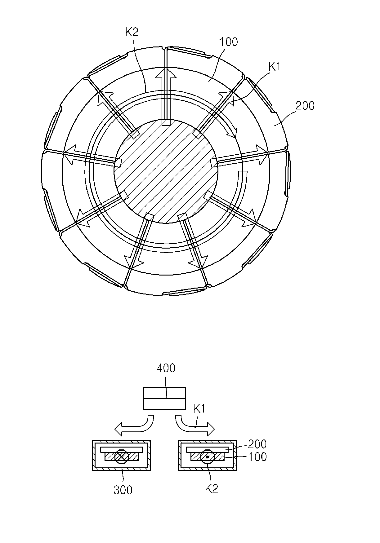
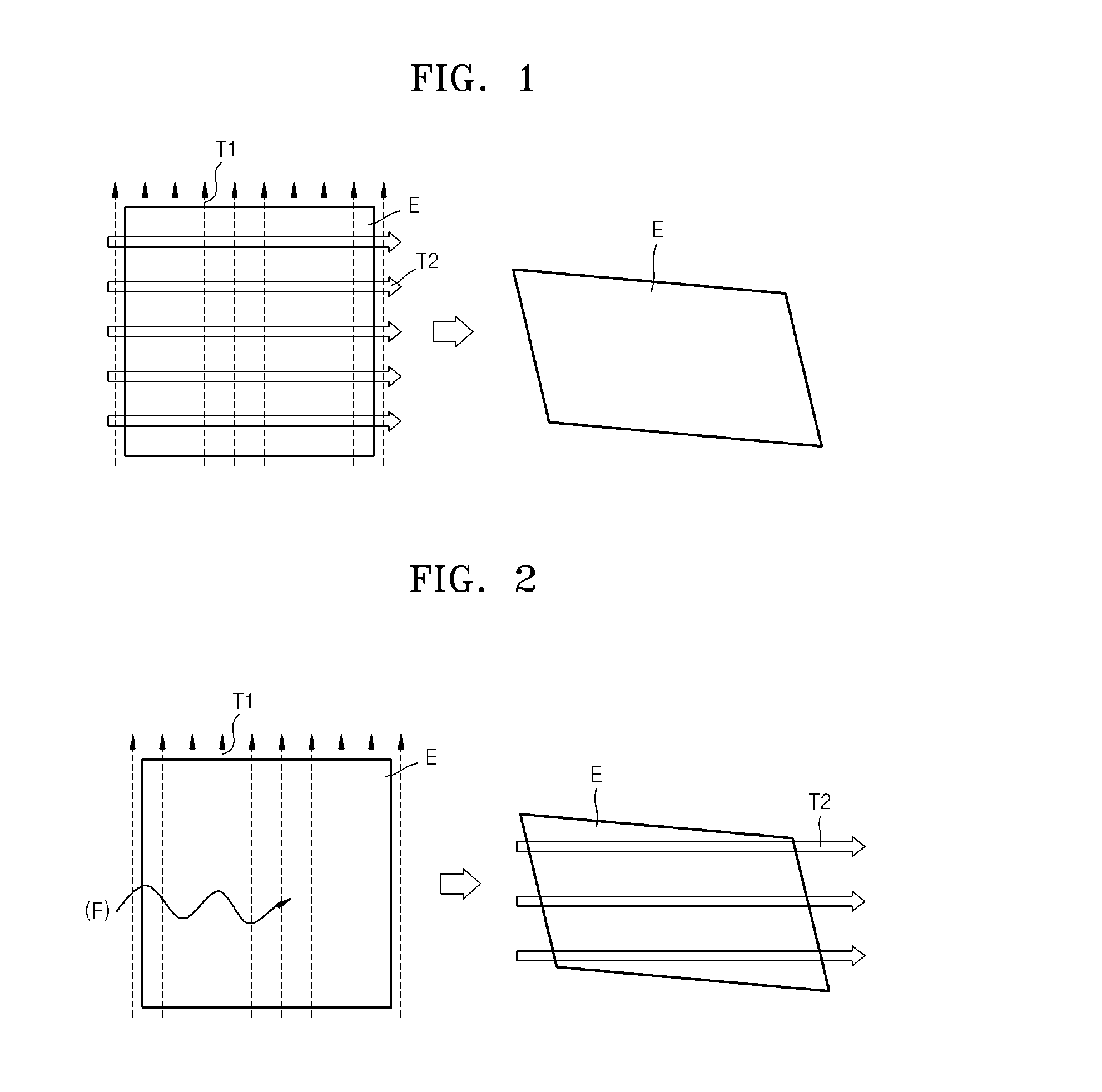
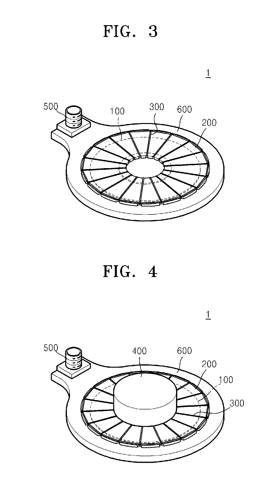
Embodiment Construction

[0033]As used herein, the term “and / or” includes any and all combinations of one or more of the associated listed items.

[0034]Hereinafter, exemplary embodiments of the present invention will be described in detail with reference to the attached drawings. The embodiments are not intended to be limitative.

[0035]Advantages, features, and a method of achieving the same will be specified with reference to embodiments that will be described in detail with reference to the attached drawings. However, the present invention will not be limited to the embodiments described below and may be embodied in various different forms. Merely, the exemplary embodiments are provided to perfectly disclose the present invention and to allow one of ordinary skill in the art to fully understand the present invention. The present invention is defined by the scope of claims thereof. Through the entire specification, like reference numerals designate like elements.

[0036]Expressions of “the left”, “the right”, ...


PUM

PropertyMeasurementUnit
magnetic fieldaaaaaaaaaa
shapeaaaaaaaaaa
radiusaaaaaaaaaa

Abstract

Provided is a transducer. The transducer includes a permanent magnet that generates a magnetostatic field, a patch disposed below the permanent magnet and formed of a material that deforms according to a magnetic field, an insulator disposed on a top surface of the patch, and a coil wound around the patch and the insulator in a certain form and allowing a magnetomotive field to be induced on the patch according to an applied current. The wound coil has a form in which directions of the magnetostatic field generated by the permanent magnet and the magnetomotive field generated by winding the coil are orthogonal to each other.

Description

CROSS-REFERENCE TO RELATED PATENT APPLICATION[0001]This application claims priority to and the benefit of Korean Patent Application No. 10-2013-0060786, filed on May 29, 2013, in the Korean Intellectual Property Office, the disclosure of which is incorporated herein in its entirety by reference.BACKGROUND OF THE INVENTION[0002]1. Field of the Invention[0003]The present invention relates to a transducer, and more particularly, to a transducer including a permanent magnet that generates a magnetostatic field, a patch disposed below the permanent magnet and formed of a material that deforms according to a variation in a magnetic field, an insulator disposed on a top surface of the patch, and a coil wound on the patch and the insulator in a certain form and inducing a magnetomotive field on the patch according to an applied current, in which the form of winding the coil is configured to be a form by which directions of the magnetostatic field generated by the permanent magnet and the ma...

Claims


Application Information

Patent Timeline
Patent Type & Authority Applications(United States)
IPC IPC(8): H01F38/00H01F41/06H01F7/02
CPCH01F38/00H01F41/06H01F7/0231B06B1/08Y10T29/49071H10N35/00G01N29/04
Inventor KIM, YOON YOUNGSEUNG, HONG MINKIM, HOE WOONG
Owner SEOUL NAT UNIV R&DB FOUND
Why Eureka
Try Eureka