
Video surveillance system with omni-directional camera

a video surveillance and omni-directional technology, applied in the field of surveillance systems, can solve the problems of increasing the number of cameras, increasing the complexity and cost of the system, and limited field of view (fov) of traditional perspective cameras

Active Publication Date: 2007-03-29
MOTOROLA SOLUTIONS INC
View PDF4 Cites 118 Cited by
  • Summary
  • Abstract
  • Description
  • Claims
  • Application Information

AI Technical Summary

Benefits of technology

[0007] Embodiments of the invention include a method, a system, an apparatus, and an article of manufacture for video surveillance. An omni-directional camera is ideal for a video surveillance system with a wider field of view because of its seamless coverage and passive, high-resolution feature.

Problems solved by technology

One significant constraint of the system is the limited field-of-view (FOV) of a traditional perspective camera.
However increasing the number of cameras increases the complexity and cost of system.
Additionally, increasing the number of cameras also increases the complexity of the video processing since targets need to be tracked from camera to camera.
In port, however, the radar is less useful due to the large amount of clutter in a busy port facility.
Furthermore, it may be undesirable or not permissible to use active radar in certain ports.
This is problematic because naval vessels are most vulnerable to attack, such as a terrorist attack, when the vessel is in port.

Method used


Image

  • Video surveillance system with omni-directional camera
  • Video surveillance system with omni-directional camera
  • Video surveillance system with omni-directional camera

Examples


Embodiment Construction

[0057] Exemplary embodiments of the invention are discussed in detail below. While specific exemplary embodiments are discussed, it should be understood that this is done for illustration purposes only. A person skilled in the relevant art will recognize that other components and configurations can be used without parting from the spirit and scope of the invention.

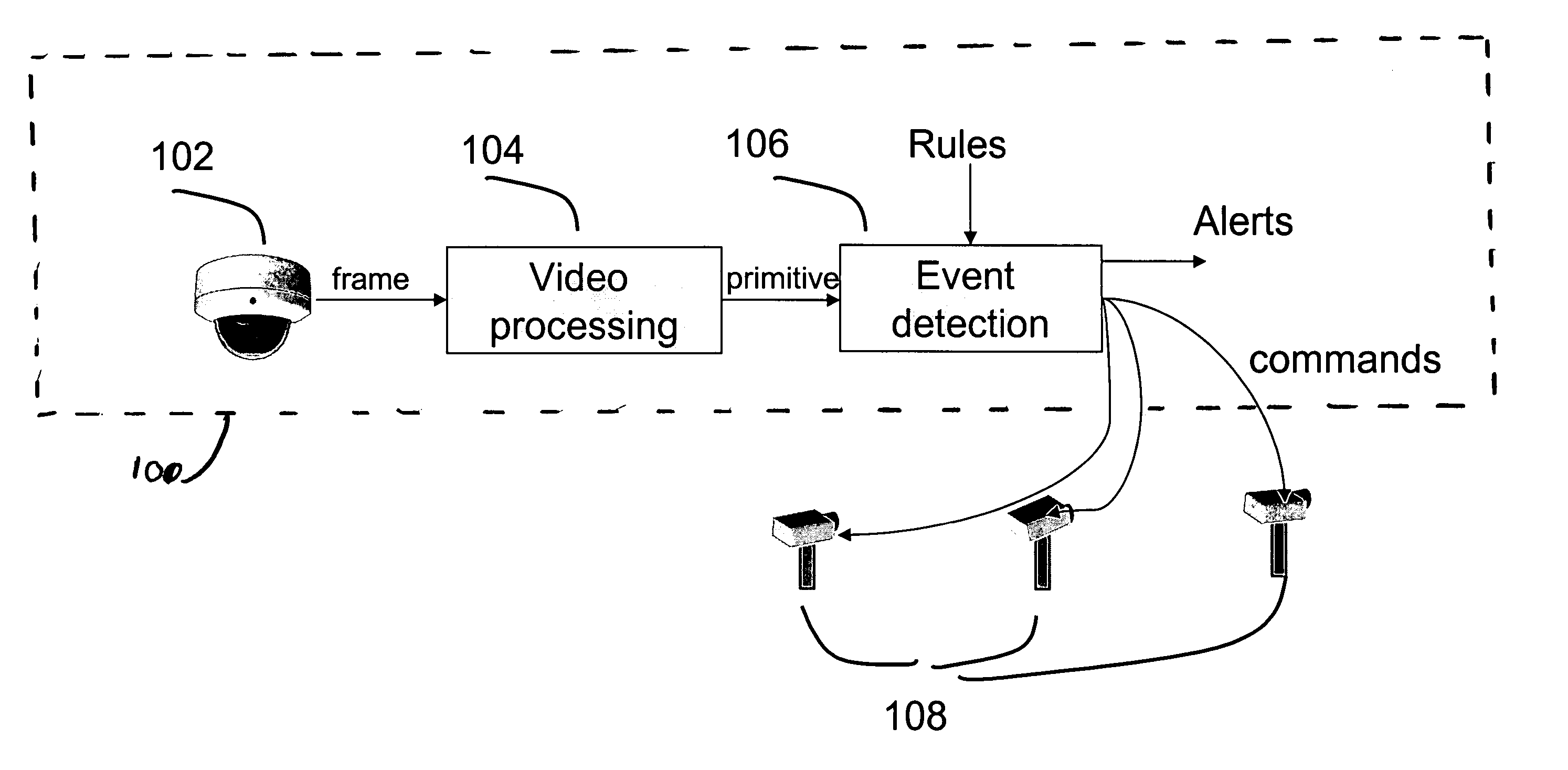
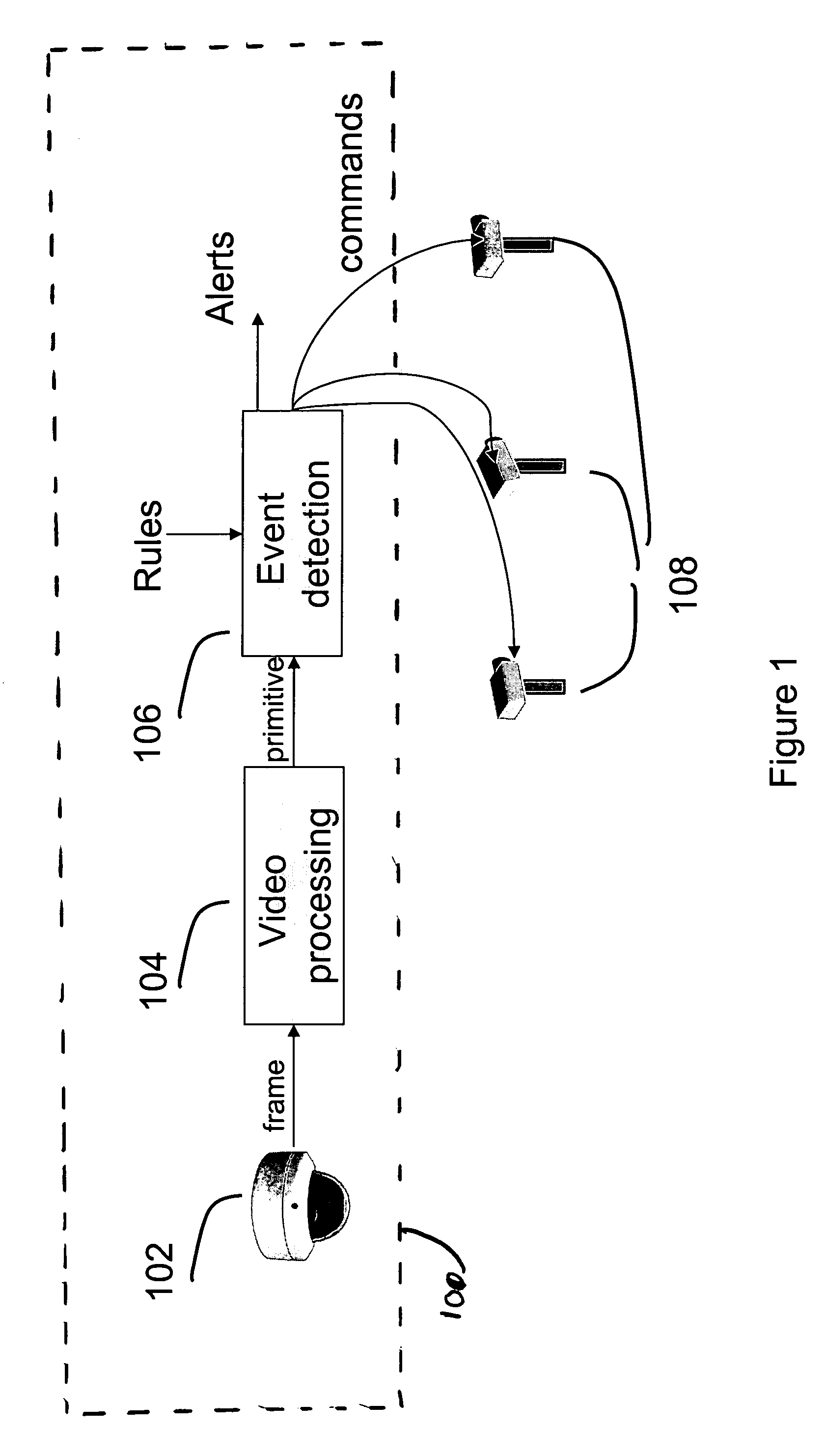
[0058]FIG. 1 depicts an exemplary embodiment of the invention. The system of FIG. 1 uses one camera 102, called the primary, to provide an overall picture of a scene, and another camera 108, called the secondary, to provide high-resolution pictures of targets of interest. There may be multiple primaries 102, the primary 102 may utilize multiple units (e.g., multiple cameras), and / or there may be one or multiple secondaries 108.

[0059] A primary sensing unit 100 may comprise, for example, a digital video camera attached to a computer. The computer runs software that may perform a number of tasks, including segmenting movin...


PUM


Abstract

A method of operating a video surveillance system is provided. The video surveillance system including at least two sensing units. A first sensing unit having a substantially 360 degree field of view is used to detect an event of interest. Location information regarding a target is sent from the first sensing unit to at least one second sensing unit when an event of interest is detected by the first sensing unit.

Description

BACKGROUND OF THE INVENTION [0001] 1. Field of the Invention [0002] This invention relates to surveillance systems. Specifically, the invention relates to a video-based surveillance system that uses an omni-directional camera as a primary sensor. Additional sensors, such as pan-tilt-zoom cameras (PTZ cameras), may be applied in the system for increased performance. [0003] 2. Related Art [0004] Some state-of-the-art intelligent video surveillance (IVS) systems can perform content analysis on frames generated by surveillance cameras. Based on user-defined rules or policies, IVS systems can automatically detect potential threats by detecting, tracking and analyzing the targets in the scene. One significant constraint of the system is the limited field-of-view (FOV) of a traditional perspective camera. A number of cameras can be employed in the system to obtain a wider FOV. However increasing the number of cameras increases the complexity and cost of system. Additionally, increasing the...

Claims


Application Information

Patent Timeline
Patent Type & Authority Applications(United States)
IPC IPC(8): H04N7/00H04N7/18
CPCG08B13/19626G08B13/19628G08B13/19682G08B13/1968G08B13/19643
Inventor YIN, WEIHONGYU, LIZHANG, ZHONGCHOSAK, ANDREW J.HAERING, NIELSLIPTON, ALAN J.BREWER, PAUL C.VENETIANER, PETER L.
Owner MOTOROLA SOLUTIONS INC
Learn More