Medical Situational Awareness System

a situational awareness and medical technology, applied in the field of networked surveillance and surveillance systems, can solve the problems of only being able to check the condition of patients, not having a system that permits the information of patients to be sent to other locations, and inadvertently waking up from bed, so as to reduce the time of convalescence, reduce injuries, and reduce the effect of deaths

Inactive Publication Date: 2012-06-07
PR NEWSWIRE
View PDF2 Cites 160 Cited by
  • Summary
  • Abstract
  • Description
  • Claims
  • Application Information

AI Technical Summary

Benefits of technology

[0014]It is an important application of video surveillance to monitor patients in hospitals, clinics, doctor's offices, in the home and the like to monitor their activity while convalescing. Patients may not be stable enough to be mobile by themselves, and they may not be competent enough to know that they should not be mobile by themselves. Video surveillance can thus be an important safety adjunct to patient care. This can contribute to fewer deaths, reduced injuries, reduced convalescence times, and save patients and insurance companies money.
[0015]In addition, in light the increasing shortage of

Problems solved by technology

Or they may inadvertently roll out of bed.
However, visible checking of the patient's condition can only be accomplished by actual visual checking of the patient where he is physically located.
Thus, typically one staff member must always be present at the station or monitoring will have gap periods when the station is unmanned.
In addition, there is not any system that permits the patient's information to be sent to other locations such as, by way of example, the location

Method used


Image

  • Medical Situational Awareness System
  • Medical Situational Awareness System
  • Medical Situational Awareness System

Examples


Embodiment Construction

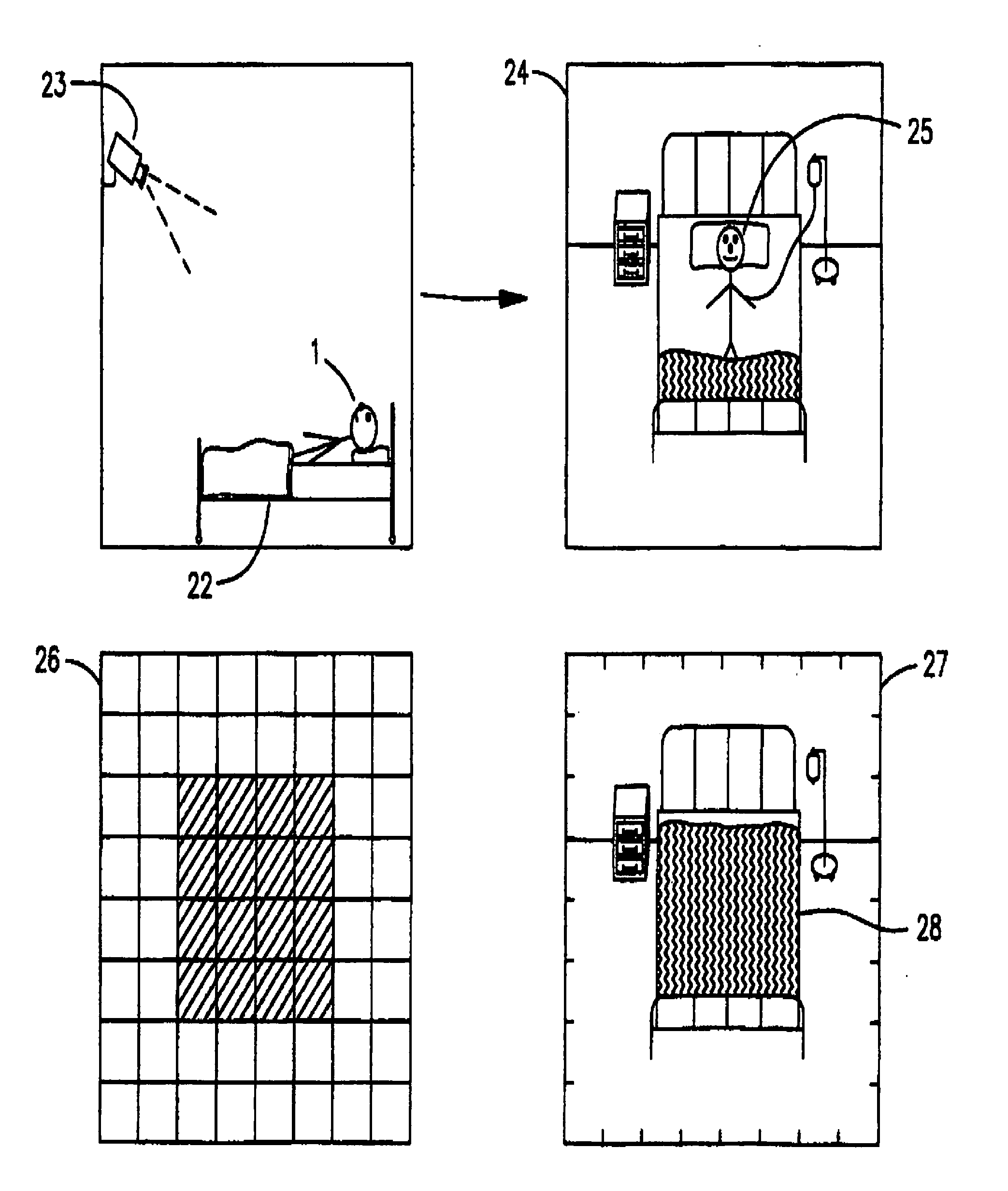
[0042]In its preferred form, the subject invention incorporates IP Video Surveillance Systems including smart cameras that have built in intelligence and IP interfaces. These cameras are incorporated in a network system utilizing centralized servers for managing and recording information which is captured by the cameras as well as legacy system information, where desired. In addition, the system is adapted for presenting video, image and other data to monitoring stations anywhere on the network, or incase of IP based systems, anywhere on the World Wide Web.

[0043]One advantage of the smart camera approach is that there is a processor at each camera or camera encoder. This allows sophisticated image analysis to be performed, which can generate alarms as has been described in my previous patents, This decentralized approach allows more sophisticated processing to be accomplished than could be done on a practical basis than could be done on a centralized system.

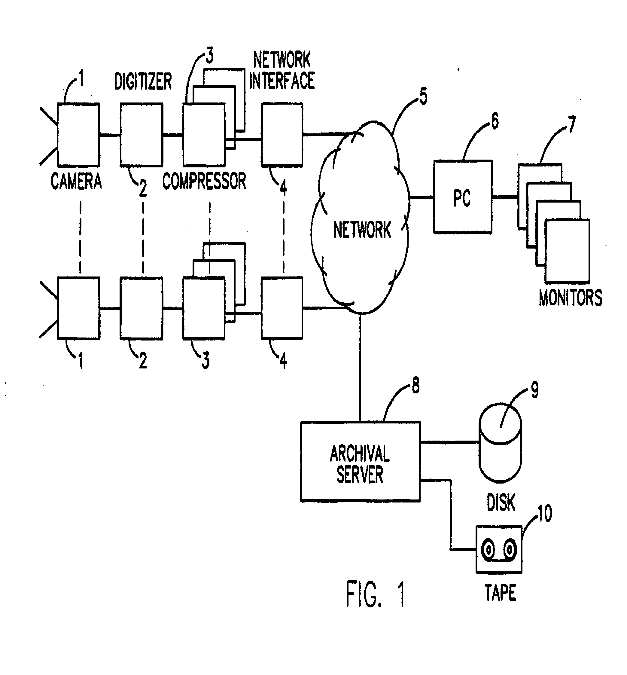
[0044]FIG. 1 summarizes t...


PUM


Abstract

The visual condition of a patient is monitored by defining a an authorized patient zone, placing a video camera in a location to capture a visual image of the patient zone, defining a base visual image of the patient zone, monitoring the visual image at a remote location, identifying any change in the captured image from the base visual image, and generating an alert in the event a change is detected. Certain changes in the zone may occur without generating an alert. Authorized personnel may enter and leave the zone without generating an alert. In a typical application the system for practicing the method is networked based for providing medical appliance data directly to key personnel at a standard computer station. The system also includes video monitoring in real-time or near real-time, providing visual as well as technical monitoring of the patient wherever he is located. In one aspect of the invention, the system is IP based, permitting access to the information anywhere on the World Wide Web.

Description

CROSS REFERENCE TO RELATED APPLICATIONS[0001]The present invention is a Continuation-In-Part of and claims priority from pending patent application Ser. No. 09 / 594,041, filed on Jun. 14, 2000, titled MULTIMEDIA SURVEILLANCE AND MONITORING SYSTEM INCLUDING NETWORK CONFIGURATION, the contents of each of which are enclosed by reference herein.[0002]The present invention is further related to patent application patent application Ser. No. 09 / 593,901, filed on Jun. 14, 2000, titled DUAL MODE CAMERA, patent application Ser. No. 09 / 593,361, filed on Jun. 14, 2000, titled DIGITAL SECURITY MULTIMEDIA SENSOR, patent application Ser. No. 09 / 716,141, filed on Nov. 17, 2000, titled METHOD AND APPARATUS FOR DISTRIBUTING DIGITIZED STREAMING VIDEO OVER A NETWORK, patent application Ser. No. 09 / 854,033, filed on May 11, 2001, titled PORTABLE, WIRELESS MONITORING AND CONTROL STATION FOR USE IN CONNECTION WITH A MULTI-MEDIA SURVEILLANCE SYSTEM HAVING ENHANCED NOTIFICATION FUNCTIONS, patent application...

Claims


Application Information

Patent Timeline
IPC IPC(8): H04N7/18
CPCH04N7/183
Inventor MONROE, DAVID A.BROWNING, JEFFREY D.
Owner PR NEWSWIRE
Why Eureka
Try Eureka