Voice coil motor

a voice coil and motor technology, applied in piezoelectric/electrostrictive transducers, optical elements, instruments, etc., can solve the problems of reducing driving efficiency, wasting electromagnetic field, and inability to interact with magnets in the corner region, and achieves enhanced magnetic field efficiency, stable and powerful pushing force, and driven by electromagnetic field

Inactive Publication Date: 2014-12-04
SILITECH TECH CORP
View PDF0 Cites 13 Cited by
  • Summary
  • Abstract
  • Description
  • Claims
  • Application Information

AI Technical Summary

Benefits of technology

[0010]In conclusion, the VCM actuator has magnet guiding tabs formed at the corners of the case and each magnet guiding tab has the pair of wing portions extending from the backbone. The magnetic field efficiency, driven by the electromagnetic field, of the coil at the corner region is enhanced thereby. The extending wing portions guide the magnetic field and condense the flux. The direction of magnetic field is ensured by the presence of the magnet guiding tabs and the flux is denser. The VCM actuator generates more stable and powerful pushing force under the same amount of current. Furthermore, the plurality of the contacting faces of the lens holder is in structural cooperation with the guiding tabs. Specifically, the magnet guiding tabs and the contacting faces of the lens holder are contiguous such that the VCM actuator can sustain stronger torsion and impact. Moreover, the annular dust proof groove formed between the dust proof ring and the base can collect or attract foreign particles therein and improve dust collection.

Problems solved by technology

However, the electromagnetic field generated by the coil at the corner region cannot interact with the magnets because the magnets are absent around the corners of the frame.
Therefore, the electromagnetic field is wasted and the driving efficiency is reduced.

Method used


Image

  • Voice coil motor
  • Voice coil motor
  • Voice coil motor

Examples


Embodiment Construction

[0022]The aforementioned illustrations and following detailed descriptions are exemplary for the purpose of further explaining the scope of the instant disclosure. Other objectives and advantages related to the instant disclosure will be illustrated in the subsequent descriptions and appended drawings.

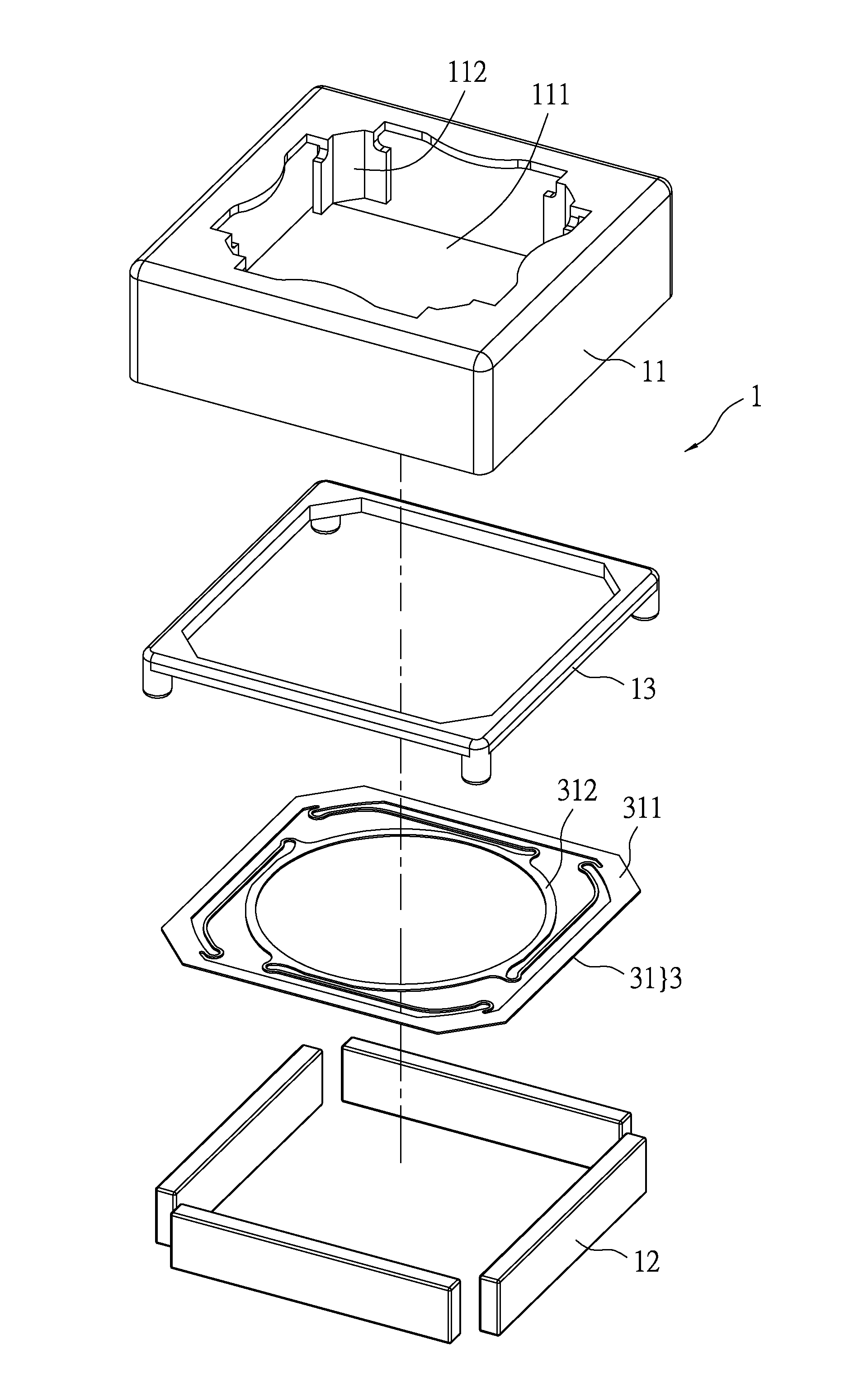
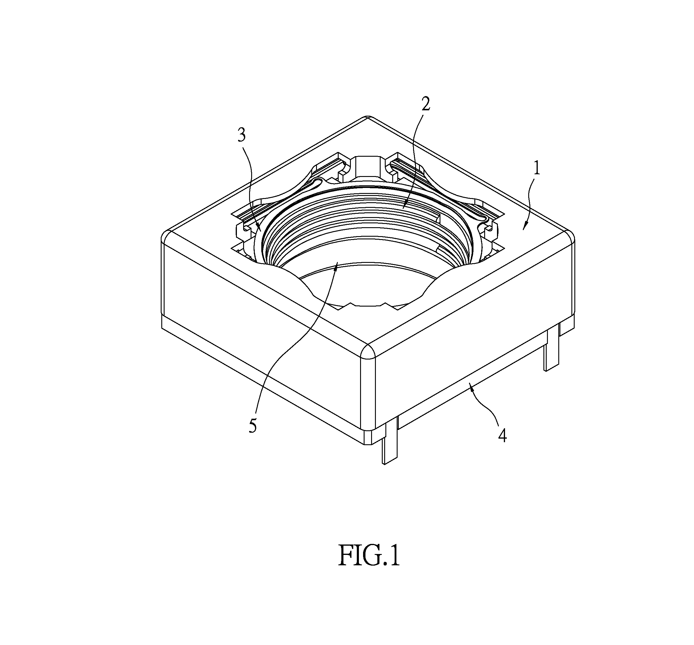
[0023]Please refer to FIG. 1 illustrating a perspective view of a voice coil motor actuator of the instant disclosure. A lens can be installed in the voice coil motor actuator and driven thereby for focusing. The voice coil actuator includes a fixed module 1, a mobile module 2 and a spring module 3. The voice coil motor actuator may further include a base 4 and a dust proof ring 5.

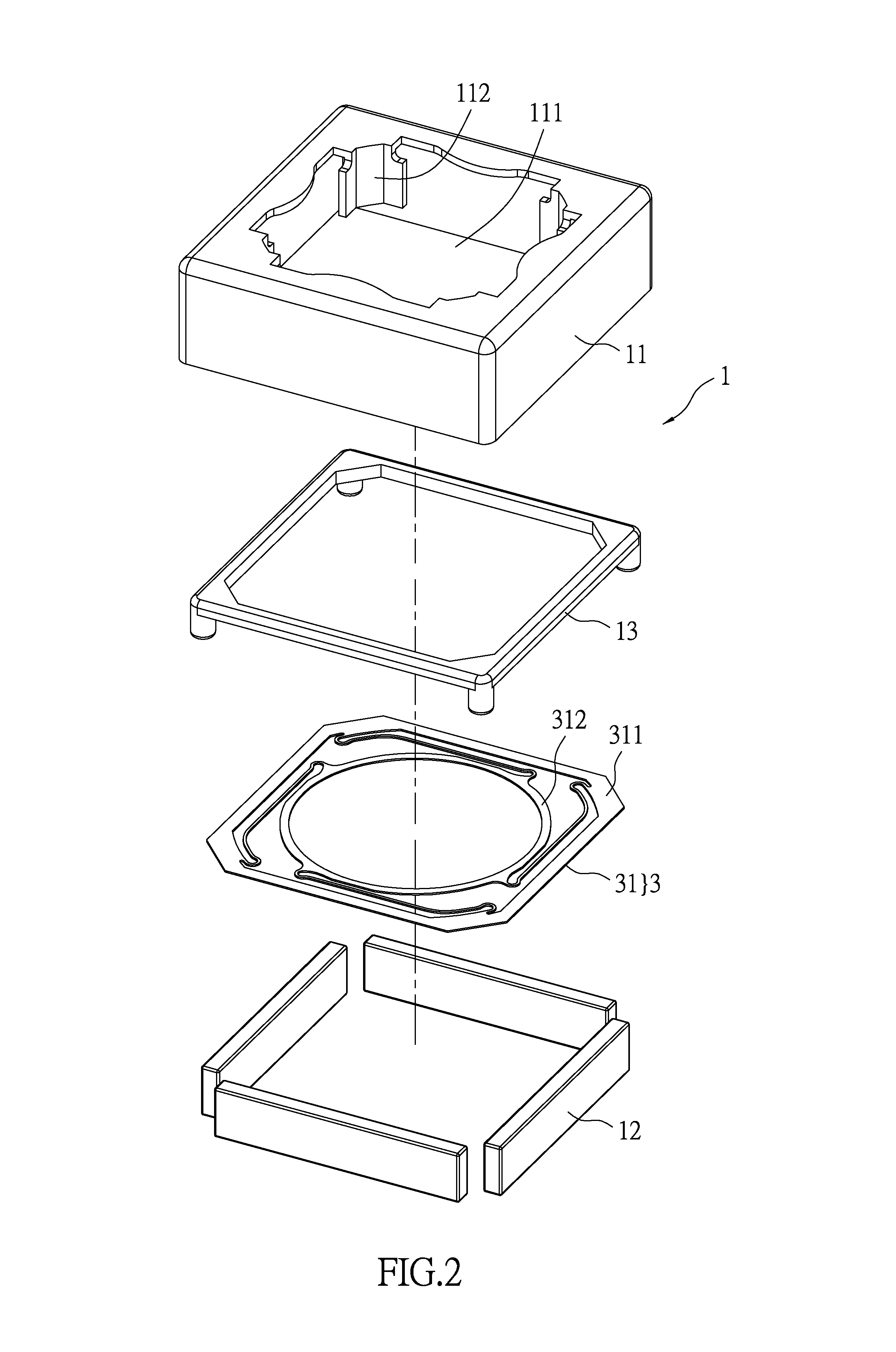
[0024]Referring FIGS. 2 to 4, the fixed module 1 includes a case 11 and a magnet module 12 being contiguous to the internal wall of the case 11. The case 11 is preferably made of metallic materials. The magnet module 12 preferably has a plurality of magnets and in the instant embodiment there are four magnets...


PUM

PropertyMeasurementUnit
pressureaaaaaaaaaa
electromagnetic fieldaaaaaaaaaa
power consumptionaaaaaaaaaa

Abstract

A VCM actuator for a lens and driving the lens for focusing includes a fixed module, a mobile module and a spring module. The fixed module includes a case and the magnet module is disposed along the inner side of the case. The mobile module includes a lens holder and a coil looping the lens holder. The lens holder is movably disposed in the case and the coil is fastened to the lens holder positioning to the magnet module. The spring module abuts the fixed module and mobile module. The case has an opening and along the rim of each corner of the opening a magnet guiding tab is formed. The guiding tabs extend between the lens holder and coil and are positioned toward the gaps between the magnet module, and each magnet guiding tab has a backbone and two wing portions extending from the backbone.

Description

BACKGROUND[0001]1. Field of the Invention[0002]The instant disclosure relates to a voice coil motor; in particular, to a voice coil motor actuator.[0003]2. Description of Related Art[0004]Conventional voice coil motor (VCM) includes a metallic frame having magnets within the frame. However, the electromagnetic field generated by the coil at the corner region cannot interact with the magnets because the magnets are absent around the corners of the frame. Therefore, the electromagnetic field is wasted and the driving efficiency is reduced. The power consumption can be relatively higher especially in a compact sized VCM.[0005]It is important to solve the abovementioned issue by structural design. A magnet seat for an auto focus camera module is disclosed by a prior art, TW 201219956. In FIG. 3 of this specification, a bended L-shaped tab 40 is formed on each corner of a frame 30. The tabs 40 extend to a receiving space 41 defined by a seat 34 and a coil 38. The L-shaped tabs 40 are pos...

Claims


Application Information

Patent Timeline
Patent Type & Authority Applications(United States)
IPC IPC(8): G02B7/04
CPCG02B7/04G02B7/08Y10T29/42
Inventor HUNG, CHIH-JUNG
Owner SILITECH TECH CORP
Why Eureka
Try Eureka