Anti-cavitation twisted rudder and design method thereof

A design method and technology of distorted rudders, which are applied in ship design, rudder steering, ships, etc., can solve the problems of increased vibration and noise, failure to consider the propeller rotation wake, increase the load of the steering gear, etc., and achieve the exciting force and radiation noise reduction, solve the problem of cavitation erosion, reduce the effect of time and area

Active Publication Date: 2017-10-20
NAVAL UNIV OF ENG PLA
View PDF4 Cites 3 Cited by
  • Summary
  • Abstract
  • Description
  • Claims
  • Application Information

AI Technical Summary

Problems solved by technology

The reason is mainly because ordinary rudders do not take into account the characteristics of the propeller's rotating wake, which leads to serious cavitation in traditional rudders.
The cavitation of the rudder will cause serious erosion of the rudder surface, which will affect the service life of the rudder, and will also cause a significant increase in vibration and noise
[0005] Since the steering force of the rudder is formed by the pressure difference between the pressure surface and the suction surface of the rudder blade, when cavitation occurs on the suction surface, the pressure remains at the saturated steam pressure and cannot be further reduced, so the rudder effect will be obvious after cavitation occurs reduce
In addition, the cavitation of the rudder will also generate a lot of noise, causing a series of adverse effects such as vibration of the rudder and the tail structure
[0006] When the ship sails straight at a rudder angle of 0°, due to the rotation of the propeller wake, the pressure distribution on the left and right sides of the rudder blade is asymmetrical, and there will be a large lateral force and rudder shaft torque on the traditional rudder. The lateral forces of the left and right rudders cancel each other out, which does not affect the ship's direct sailing performance, but the existence of the torque of the rudder shaft will increase the load on the steering gear

Method used


Image

  • Anti-cavitation twisted rudder and design method thereof
  • Anti-cavitation twisted rudder and design method thereof
  • Anti-cavitation twisted rudder and design method thereof

Examples


Embodiment Construction

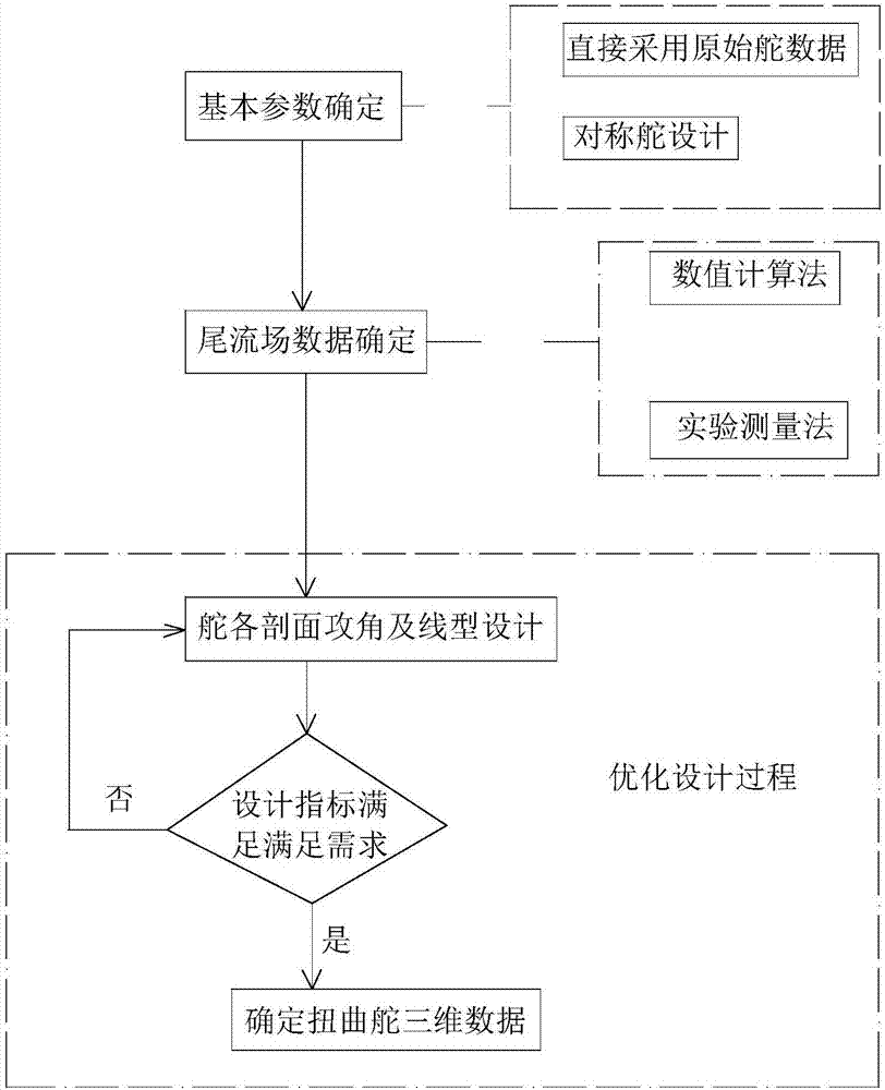
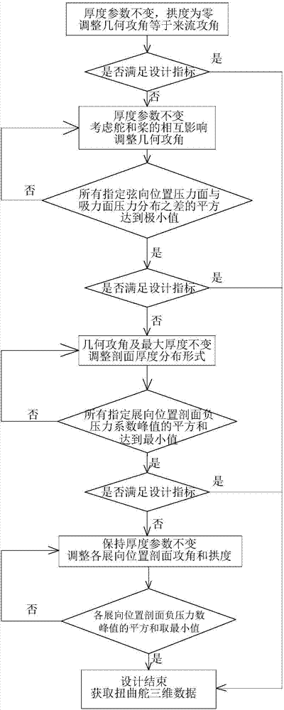
[0051] The anti-cavitation twisted rudder of the present invention and its design method are described in detail below in conjunction with the specific design process, and the schematic flow chart of its design process is as follows figure 1 and figure 2 shown, including:

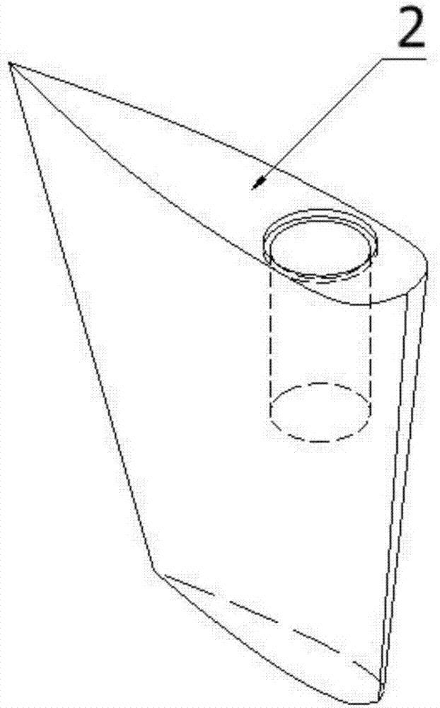
[0052] 1. Use the traditional symmetrical rudder design method to determine the rudder height of the target ship (such as Figure 14 middle L), the chord length of the section at each spanwise position, and the maximum thickness of the section at each spanwise position (such as Figure 16 Middle T), the line shape of each spanwise position section (including the distribution of thickness along the chord direction and the distribution of camber along the chord direction), and the installation position of the rudder shaft on the rudder.

[0053] In order to facilitate the operation, in this step, the geometric angle of attack of the sections at each spanwise position can be set to 0, and the linetype of th...


PUM


Abstract

The invention belongs to the field of ship or rudder design and particularly relates to an anti-cavitation twisted rudder and a design method thereof. On the basis that the influence of various factors such as the rotational speed in the ship propeller wake flow on the rudder is fully considered, the geometrical attack angles and line types of all the spanwise position sections are designed and determined through the distribution characteristic of a propeller rear wake flow field in direct sailing of a ship, so that the geometrical shape of the rudder is matched with that of the propeller wake flow field, and the purposes that the pressure distribution of the rudder surface is improved, the cavitation starting sailing speed of the rudder is increased, the time of rudder cavitation is shortened, the area of rudder cavitation is decreased, vibration and noise caused by the rudder are reduced, cavitation denudation of the rudder surface is restrained, the maintenance cost of the rudder is saved, the force state of rudder blades is improved, the rudder efficiency is improved, and the load of the rudder is reduced are achieved.

Description

technical field [0001] The invention belongs to the field of ship or ship rudder design, in particular to an anti-cavitation twisted rudder and a design method thereof. Background technique [0002] In recent years, due to the development of high-speed and large-scale ships, especially for high-speed ships, the vibration and cavitation erosion of the rudder blades working behind the propellers are becoming more and more serious, so the consideration of rudder performance is becoming more and more comprehensive. . The left and right sides of the traditional rudder blade are in a symmetrical form with the center plane of the rudder. This shape feature does not take into account the impact of the strong rotating wake of the propeller on the rudder blade, which leads to serious cavitation in traditional rudder blades. Not only will it cause cavitation erosion on the surface of the rudder blade, but it will also lead to a substantial increase in vibration and noise. [0003] Du...

Claims


Application Information

Patent Timeline
Patent Type & Authority Applications(China)
IPC IPC(8): B63H25/38B63B9/00
CPCB63B71/00B63H25/38
Inventor 叶金铭王威于安斌张凯邵涛
Owner NAVAL UNIV OF ENG PLA
Why Eureka
Try Eureka