Vertical axis wind turbine blade module and synthesized jet control method thereof
A technology of wind turbine blades and synthetic jets, which is applied in the control of wind turbines, wind turbines at right angles to the wind direction, wind turbines, etc., and can solve periodic changes in blade angle of attack, system reliability decline, and complex flow field structures, etc. problems, to achieve the effect of improving aerodynamic performance, reducing wake strength, and low power consumption
- Summary
- Abstract
- Description
- Claims
- Application Information
AI Technical Summary
Problems solved by technology
Method used
Image
Examples
Embodiment 1
[0081] Figure 7 is the Lamuda type synthetic jet control function and its schematic diagram in the embodiment of the present invention.
[0082] like Figure 7 shown in the figure
[0083]
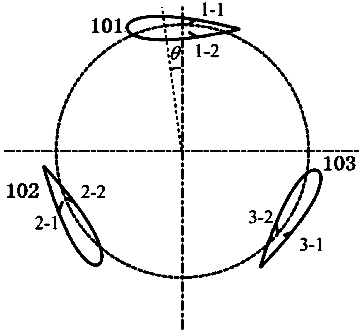
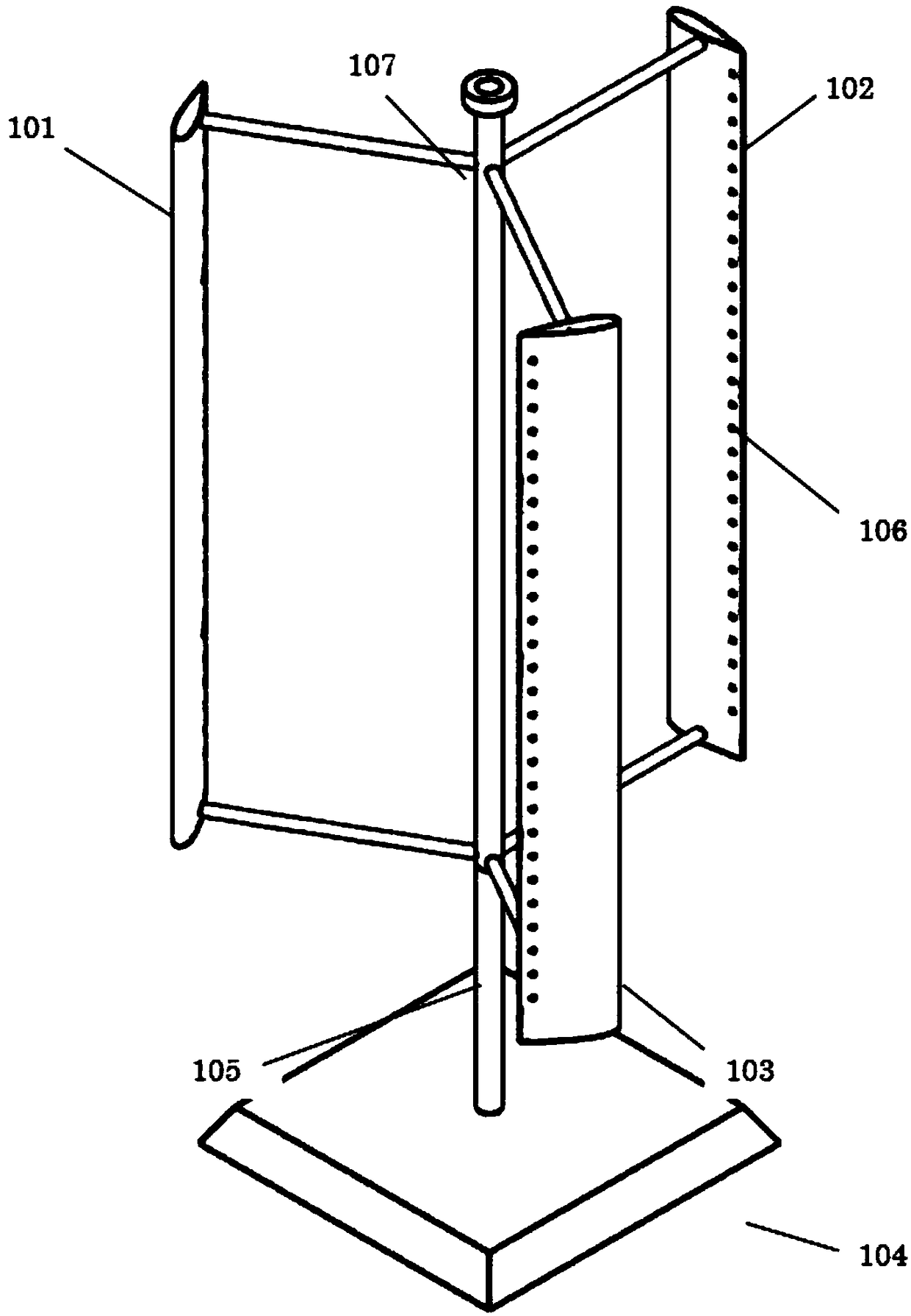
[0084] When the jet hole 106 is on the pressure side of the blade, the jet is closed, and when it is on the suction side, the jet is turned on, and the fluid is blown / absorbed at a certain working frequency; the amplitude of the piezoelectric film can be controlled, and the excitation frequency of the exciter can also be controlled to make the jet blowing coefficient C μ As the effective angle of attack of the blade increases, the jet blowing coefficient C at zero angle of attack μ is 0. combine figure 1 , the initial position of jet hole 1-1 is on the pressure surface of the blade, and the initial position of jet hole 1-2 is on the suction surface of the blade, so jet hole 1-2 should open the jet, and the jet blowing coefficient C μ size should vary with Figure 7 The Lamuda contr...
Embodiment 2
[0086] Figure 8 is the piecewise linear synthetic jet control function and its schematic diagram in the embodiment of the present invention.
[0087] like Figure 8 shown in the figure
[0088] When the jet hole 106 is on the pressure side of the blade, the jet is closed, and when it is on the suction side, the jet is turned on, and the fluid is blown / absorbed at a certain working frequency; the amplitude of the piezoelectric film can be controlled, and the excitation frequency of the exciter can also be controlled, so that the jet blowing coefficient can be adjusted accordingly. The effective angle of attack of the blade increases, and the blowing coefficient of the jet is 0 when the angle of attack is zero. combine figure 1 , the starting position of jet hole 1-1 is on the pressure surface of the blade, and the starting position of jet hole 1-2 is on the suction side of the blade, so jet hole 1-2 should open the jet, and the jet blowing coefficient should vary with F...
Embodiment 3
[0090] Figure 9 is the Sin-type synthetic jet control function and its schematic diagram in the embodiment of the present invention.
[0091] like Figure 9 shown in the figure
[0092] When the jet hole 106 is on the pressure side of the blade, the jet is closed, and when it is on the suction side, the jet is turned on, and the fluid is blown / absorbed at a certain working frequency; the amplitude of the piezoelectric film can be controlled, and the excitation frequency of the exciter can also be controlled, so that the jet blowing coefficient can be adjusted accordingly. The effective angle of attack of the blade increases, and the blowing coefficient of the jet is 0 when the angle of attack is zero. combine figure 1 , the starting position of jet hole 1-1 is on the pressure surface of the blade, and the starting position of jet hole 1-2 is on the suction side of the blade, so jet hole 1-2 should open the jet, and the jet blowing coefficient should vary with Figure 9 ...
PUM
 Abstract
Description
Claims
Application Information
 - R&D
- Intellectual Property
- Life Sciences
- Materials
- Tech Scout
- Unparalleled Data Quality
- Higher Quality Content
- 60% Fewer Hallucinations
Browse by: Latest US Patents, China's latest patents, Technical Efficacy Thesaurus, Application Domain, Technology Topic, Popular Technical Reports.
© 2025 PatSnap. All rights reserved.Legal|Privacy policy|Modern Slavery Act Transparency Statement|Sitemap|About US| Contact US: help@patsnap.com


