Moving blade set of turbomachine

A technology for moving blades and turbines, which is applied in the directions of machines/engines, blade supporting elements, mechanical equipment, etc., and can solve problems such as cracks in moving blades and breaking of supporting fins.

Inactive Publication Date: 2004-10-06
SIEMENS AG
View PDF7 Cites 13 Cited by
  • Summary
  • Abstract
  • Description
  • Claims
  • Application Information

AI Technical Summary

Problems solved by technology

[0010] Some prior art possibilities for damping the vibrations of the moving blades have the disadvantage that the moving blades have to be tensioned against each other by means of support fins or the like, which on the one hand reduces the vibrations but On the other hand an additional mechanical load is generated due to tension
This mechanical load can lead to cracks in the rotor blades
In addition, support fins or similar components of the prior art have such a large spatial extension that considerable centrifugal forces are generated during operation, which can cause the support fins to snap off

Method used


Image

  • Moving blade set of turbomachine
  • Moving blade set of turbomachine
  • Moving blade set of turbomachine

Examples


Embodiment Construction

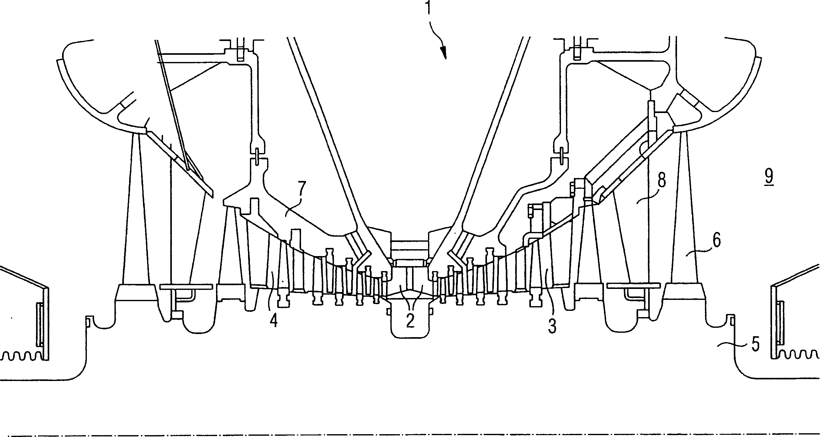
[0023] figure 1 A partial section of a low-pressure steam turbine 1 is depicted. A flow medium flows through the flow channels 3 , 4 after passing through the inflow region 2 . A rotatably mounted rotor 5 has different rotor blade sets spaced apart from one another in the axial direction, of which only one rotor blade set 6 is designated with reference numeral 6 for the sake of clarity. Guide vanes 8 are mounted on the inner housing 7 . The expanded steam is discharged from the low-pressure steam turbine 1 via the outflow line 9 . During operation of the steam turbine, the rotor 5 rotates about the axis of rotation 10 .

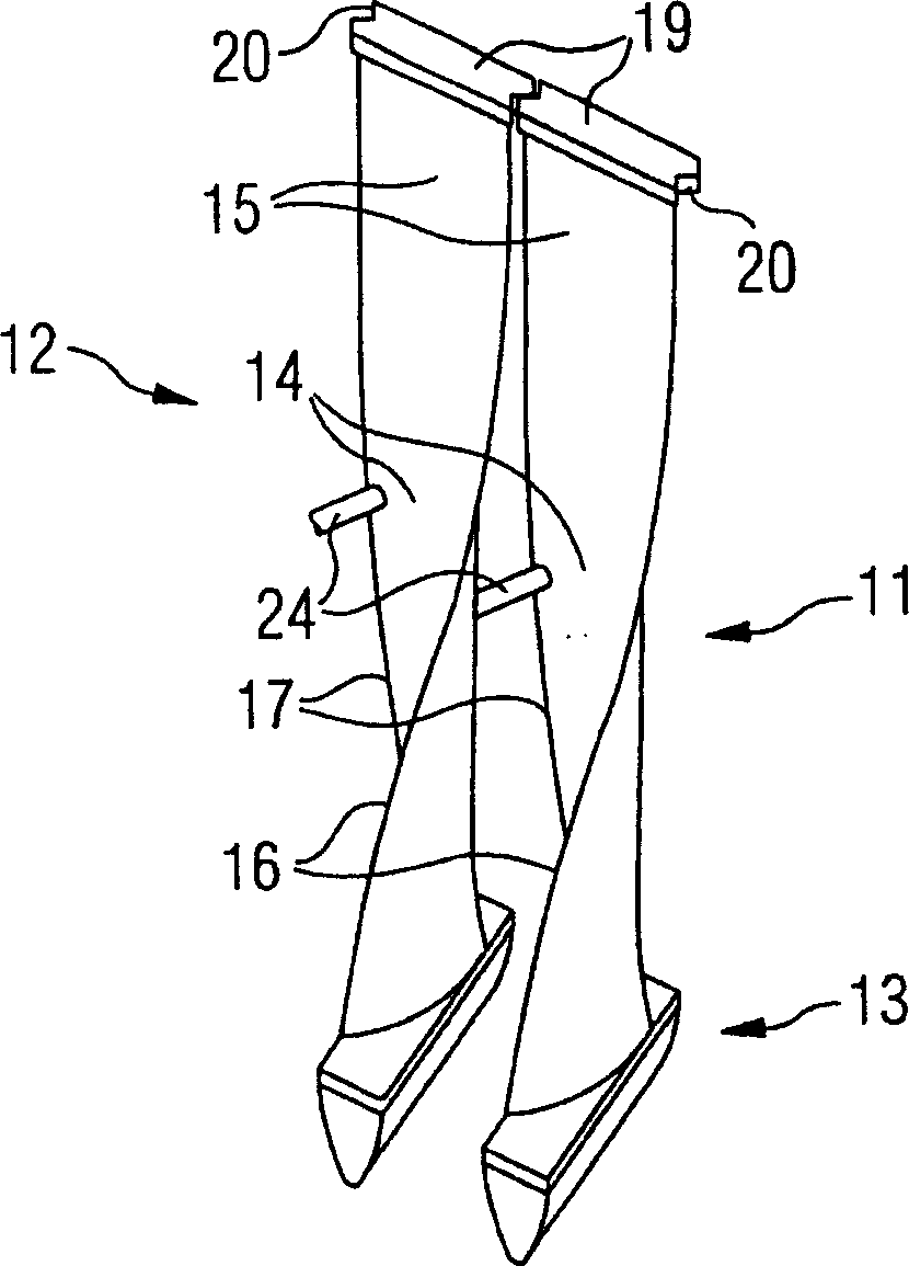
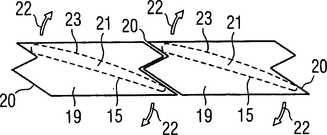
[0024] figure 2 Two rotor blades 11 , 12 of a rotor blade set 6 are depicted. The rotor blades 11 , 12 have a rotor blade root 13 , a rotor blade center 14 and a rotor blade end 15 . Furthermore, the rotor blades 11 , 12 have a leading edge 16 and a trailing edge 17 . A vertical cover plate 19 perpendicular to the radial direction 18 of the moving bla...


PUM


Abstract

Two adjacent blades (11,12) may be connected together by narrow circular-section rods (24) on their mid portions (14). The roots of the blades have standard root mountings (13). The leading edges (16) and trailing edges (17) of the blades are twisted and cambered for maximum performance. Each blade has a shroud segment (19) at its tip (15), interlocking (20) with the adjacent shroud segment.

Description

technical field [0001] The invention relates to a moving blade set of an axial flow turbine or compressor. Background technique [0002] In the steam turbine structure, especially in the low pressure area, the moving blade set with a large upstream surface is installed. The radial dimension of each blade in such a moving blade set is relatively long. Such moving blades can be more than one meter long. At the speeds achievable during operation, the centrifugal forces on the rotor blades are so high that lightweight materials must be used. For this reason, titanium or titanium alloys were chosen and are currently often used in the construction of steam turbines. Due to the low density of titanium or titanium alloy, the centrifugal force on the moving blade made of titanium or titanium alloy is not large. The disadvantage in this case is the low inherent damping of such moving blades. During operation, such rotor blades made of titanium or titanium alloys in the rotor blad...

Claims


Application Information

Patent Timeline
Patent Type & Authority Applications(China)
IPC IPC(8): F01D5/22F01D5/24F01D5/28F01D25/00F04D29/38F04D29/66
CPCF01D5/24F05D2300/133
Inventor 克里斯托弗·里克特海音里希·斯图尔弗兰克·特鲁肯米勒
Owner SIEMENS AG
Why Eureka
Try Eureka