Pressure pipe with formed connecting head

A pressure pipe, pressure technology, applied in the direction of pipes/pipe joints/pipes, connections for packing and sealing with fluid pressure, pipes, etc., can solve cumbersome problems, reduce the formation of upsetting wrinkles, and improve the strength of use.

Active Publication Date: 2007-05-09
MAN ENERGY SOLUTIONS SA
View PDF2 Cites 7 Cited by
  • Summary
  • Abstract
  • Description
  • Claims
  • Application Information

AI Technical Summary

Problems solved by technology

The disadvantage of this prior art is the use of cumbersome stepped lugs and the inability to

Method used


Image

  • Pressure pipe with formed connecting head
  • Pressure pipe with formed connecting head
  • Pressure pipe with formed connecting head

Examples


Embodiment Construction

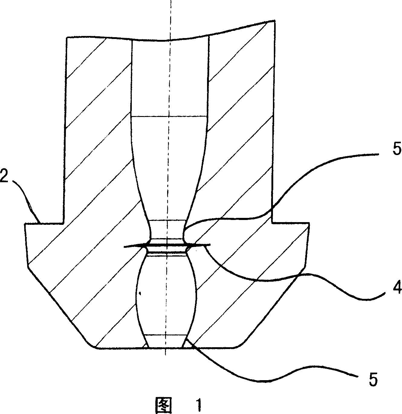
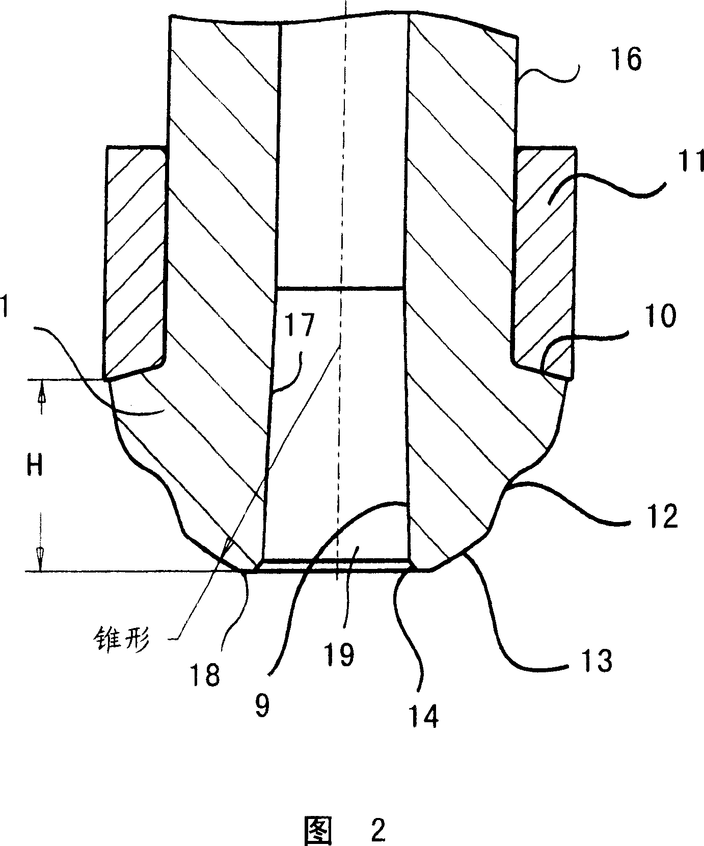
[0027] FIG. 2 shows the pipe end of a fuel injection pipe with connection 1 and line 16 . The beveled pressure shoulder 10 bears on a pressure ring 5 which is required for tightening, for example using a union nut (not shown). The envelope surface of the frusto-conical joint has both a concave arc 12 and a sealing surface 13 . The sealing surface 13 serves to seal the pressure pipe against a counterpart from the injection system (not shown). An inner cone 9 is formed in the region of the joint on the inner surface 17 of the pressure tube. The inner cone 9 forms a tube opening 19 on the top surface 18 . The pressure shoulder 10 forms an angle of greater than 90° with the outer surface of the pressure tube 16 . This angle is preferably between 100° and 110°. The loading of the pressure ring 11 is favorable in this angular range. The height H of the joint also has an effect on the formation of upset folds and should lie in the range of 0.5 to 1.0 times the outer diameter for...


PUM


Abstract

The pressure line, for example as a high-pressure fuel injection line, has a cold-worked connection (1) at the end of the line (16). The joint (1) is frustoconical and has a surrounding sealing surface on its enveloping surface, which is pressed against the connection part with a corresponding fit by means of a preload transmitted via the pressure shoulder (10). Wherein the outer surface of the pipe (16) encloses an angle greater than 90° with a surface of the pressure shoulder (10).

Description

technical field [0001] The invention relates to a pressure pipe with a formed joint, and in particular a high-pressure fuel injection pipe with an upset joint. Background technique [0002] The pressure line, which is the object of the invention, is used as a fuel injection line for conveying fuel on an injection system or as a hydraulic line. In order to be able to tightly connect the pressure tube to other components, the end of the pressure tube is made frusto-conical. Cold working is used in the prior art as an economical variant for producing such joints. The results of the methods known from the prior art are shown, for example, in the publications US 6,286,556 B1 and DE 103 58 373 A1 by means of fuel pipes. [0003] This prior art is also shown in Figure 1, showing in section the frusto-conical joint and the pipe interior deformed by pressure pipe upset. In this embodiment of the prior art, the sealing of the part to which the pressure tube is to be connected is ac...

Claims


Application Information

Patent Timeline
IPC IPC(8): F16L19/028F02M55/02B21J13/02
CPCB21K21/12F02M55/005F16L9/00F16L17/00
Inventor L·普罗尔W·罗迪格W·瓦格纳J·温特H·亚尔辛
Owner MAN ENERGY SOLUTIONS SA
Why Eureka
Try Eureka