End mill with high ramp angle capability

a technology of ramp angle and end mill, which is applied in the direction of adverse effect compensation, milling equipment, metal-working apparatus, etc., can solve the problems of ramp milling being less productive, end milling not being the first choice, and end milling being the least stable of all milling cutters

Inactive Publication Date: 2014-12-04
KENNAMETAL INC
View PDF12 Cites 17 Cited by
  • Summary
  • Abstract
  • Description
  • Claims
  • Application Information

AI Technical Summary

Benefits of technology

[0018]The problem of designing an end mill that is capable of an extremely high ramp angle (i.e., at least ten (10) degrees) is solved by providing an end mill having a cutting tip with a double positive geometry (i.e., both positive axial and radial rakes on both the leading and trailing edges) when the trailing face contacts the work during a ramp operation without contacting the work at the center of the end mill.
[0019]In one aspect of the invention, a rotary cutting tool with a longitudinal axis comprises a shank portion; a cutting portion extending from the shank portion to a cutting tip, the cutting portion having a length of cut, and a plurality of blades separated by flutes extending along the length of cut, each of the blades including a leading face, a trailing face, a land surface extending between the leading face and the trailing face, and a cutting edge at the intersection between the leading face and the land surface, the cutting tip comprising a corner radius, a first portion proximate an outer diameter of the rotary cutting tool, a third portion proximate the central axis, and a second portion between the first and third portions, wherein the trailing face contacts a work during a ramp operation in such a way that the first, second and third portions of the cutting tip have a double positive geometry, thereby enabling the rotary cutting tool to perform the ramp operation with a ramp angle of at least ten degrees.
[0020]In another...

Problems solved by technology

However, because of full engagement in the periphery, poor chip formation, and evacuation, end mills are not a first choice for slotting operations.
While very versatile, end mills are the least stable of all m...

Method used


Image

  • End mill with high ramp angle capability
  • End mill with high ramp angle capability
  • End mill with high ramp angle capability

Examples


Embodiment Construction

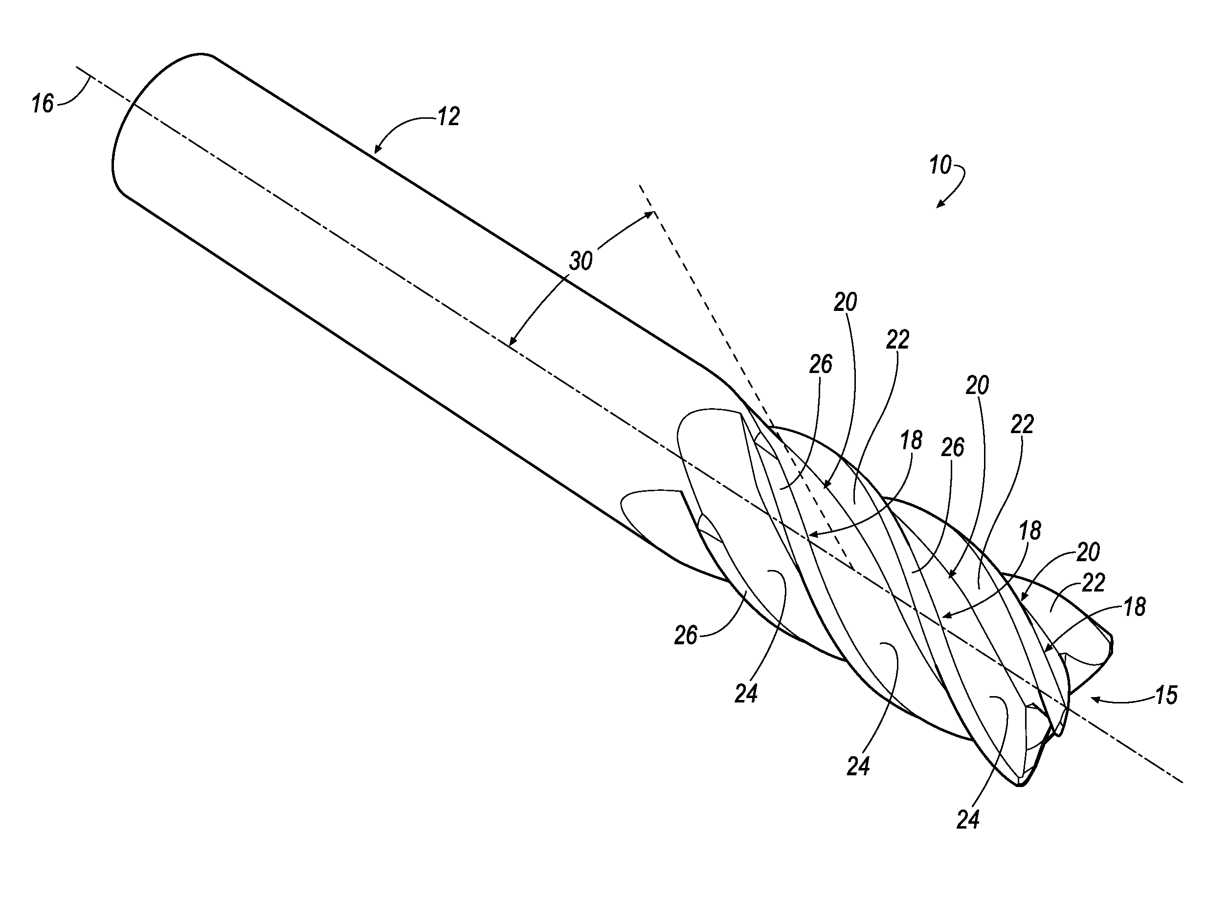
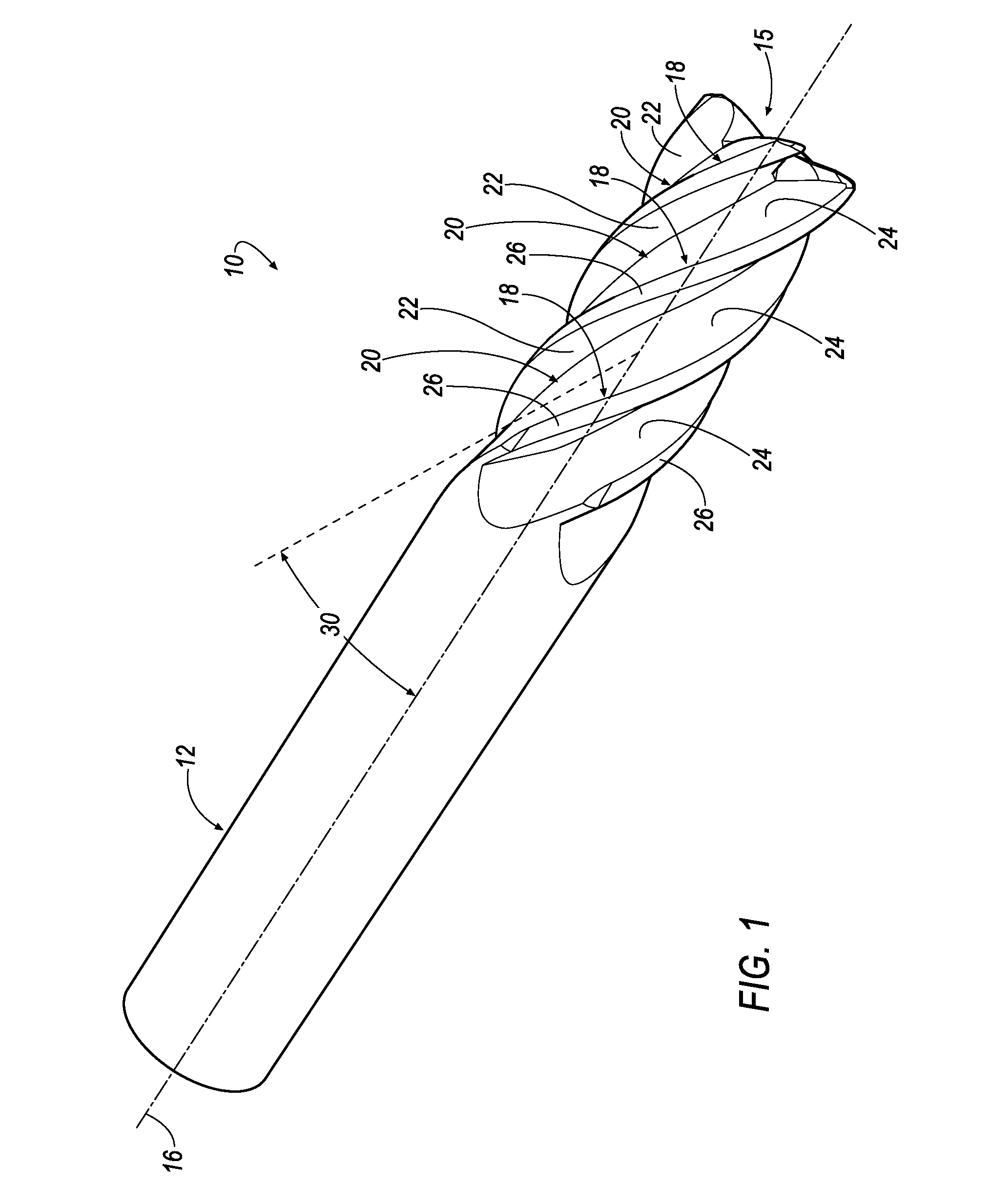
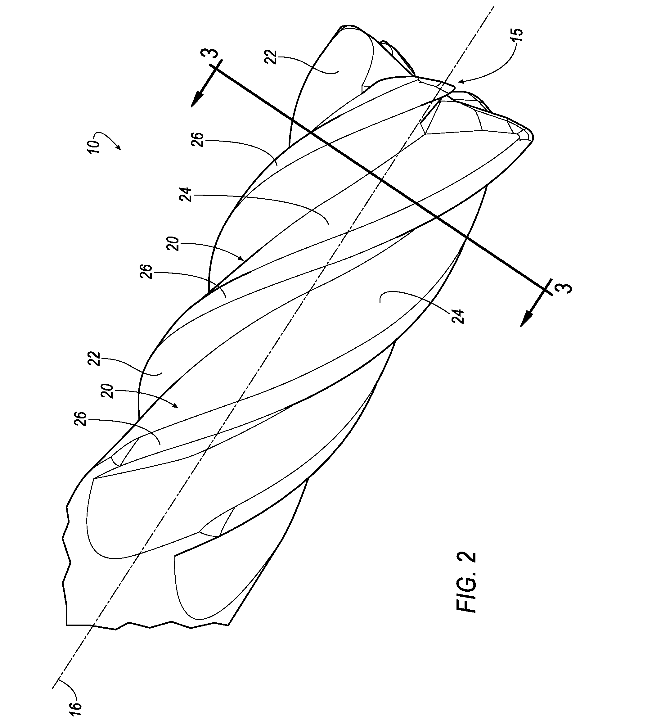
[0029]Referring now to FIGS. 1-3, a rotary cutting tool 10 is provided that includes a shank portion 12, a cutting portion 14 having a cutting tip 15, and a longitudinal axis 16. In the illustrated embodiment, the rotary cutting tool 10 comprises a solid end mill having a cutting diameter, D (FIGS. 3 and 6). The overall shape of the cutting portion 14 may be, but is not limited to, a cylindrical shape or a frusto-conical shape. The cutting portion 14 includes a plurality of blades 18 separated by flutes 20 extending the length of the cutting portion 14. The end mill 10 rotates in a direction of the arrow, R (FIGS. 3 and 6). Each of the blades 18 has a leading face 22, a trailing face 24, and a land surface 26 bridging the leading face 22 and trailing face 24. The intersection between the leading face 22 and the land surface 26 forms a cutting edge 28 for the respective blade 18.

[0030]As used herein, axial rake angle is defined as the angle between the cutter tooth face of a blade of...


PUM

PropertyMeasurementUnit
Angleaaaaaaaaaa
Angleaaaaaaaaaa
Angleaaaaaaaaaa

Abstract

A rotary cutting tool with a longitudinal axis includes a shank portion, a cutting portion, and a cutting tip. The cutting portion includes a plurality of blades and a plurality of flutes. Each blade includes a leading face, a trailing face, and a land surface extending between the leading face and the trailing face. The cutting tip includes a corner radius, a first portion formed with a first dish angle, and second portion formed with a second dish angle and a third portion formed with a third dish angle. The trailing face contacts the work during a ramp operation in such a way that the first, second and third portions have a double positive geometry to provide the cutting tool with high ramp angle capability.

Description

FIELD OF THE INVENTION[0001]The invention pertains to a rotary cutting tool. More particularly, the invention relates to a solid end mill having a double positive end geometry (i.e., positive axial and radial rakes on both the leading and trailing edges) that enables the end mill to perform a ramp operation at an extremely high ramp angle.BACKGROUND OF THE INVENTION[0002]At its most basic, milling is the meeting of a rotating tool with a clamped and stationary workpiece, as opposed to turning where the tool is stationary and the work material rotates. Actually, the workpiece has feed motion imparted from the machine tool. The meeting of the rotary motion of the cutter and the cutting edge of the tools produces fluctuating cutting forces: vibration, heat, and, if all goes well, chips.[0003]Milling machines may have either vertical or horizontal spindle orientation, and typically, face milling cuts flat surfaces, but multi-axis CNC machines make it possible to include three-dimensiona...

Claims


Application Information

Patent Timeline
IPC IPC(8): B23C5/10B23C5/28
CPCB23C5/10B23C5/28B23C2210/045B23C2250/12B23C2210/0485B23C2210/40B23C2210/0457Y10T407/14Y10T407/1948
Inventor DAVIS, DANNY RAY
Owner KENNAMETAL INC
Why Eureka
Try Eureka