Bundled object, bundling method, and bundling apparatus

a technology of bundling method and object, which is applied in the directions of bundling machine details, paper/cardboard containers, bundling articles, etc., can solve the problem of difficulty in saying that a plurality of articles can be sufficiently strong bundled, and achieve the effect of easy torn o

Active Publication Date: 2014-12-11
FUJIFILM CORP
View PDF6 Cites 1 Cited by
  • Summary
  • Abstract
  • Description
  • Claims
  • Application Information

AI Technical Summary

Benefits of technology

[0011]In the bundled object described in JP1987-4088A (JP-S62-4088A), one end and the other end of the packaging band are joined to each other so as to be able to be easily torn off, and thus releasing the bundling is simple, whereas a possibility that during transport or the like, the joining may come off, whereby the bundling may be loosened is recognized. Further, also in the bundled object described in JP2002-211633A, releasing the bundling is simple, whereas it is difficult to say that a plurality of articles can be sufficiently strongly bundled.
[0012]The present invention has been made in view of the above-described circumstances and has an object to provide a bundled object in which a plurality of overlapped articles is sufficiently strongly bundled and on the other hand, it is also easy to release the bundling.
[0013]Further, the present invention has an object to provide a bundling method and a bundling apparatus in which it is possible to manufacture the bundled object as described above.

Problems solved by technology

Further, also in the bundled object described in JP2002-211633A, releasing the bundling is simple, whereas it is difficult to say that a plurality of articles can be sufficiently strongly bundled.

Method used


Image

  • Bundled object, bundling method, and bundling apparatus
  • Bundled object, bundling method, and bundling apparatus
  • Bundled object, bundling method, and bundling apparatus

Examples


example

Preferable Range of Bundling Force

[0126]Next, a preferable range of a force to bundle the laminated body 3 will be described. Here, with respect to the tensile strength of the plastic tape 4, what extent is preferable to be selected as a bundling force of a ratio was determined by experiment. In addition, the “tensile strength” of the plastic tape 4 which is dealt with here is defined by the lowest tensile stress in which the elasticity thereof is lost, that is, stress in which the plastic tape 4 starts plastic deformation if the plastic tape 4 is pulled with a further force. The reason for focusing on the elasticity of the plastic tape 4 is because, in order to strongly bundle the laminated body 3 composed of a plurality of articles laminated, it becomes essential to elastically bundle the laminated body 3 with the tape 4.

[0127]a. Test Conditions

[0128]In the experiment, the bundling strength was evaluated with the bundled object 1 as a target, in which the laminated body 3 made by ...


PUM


Abstract

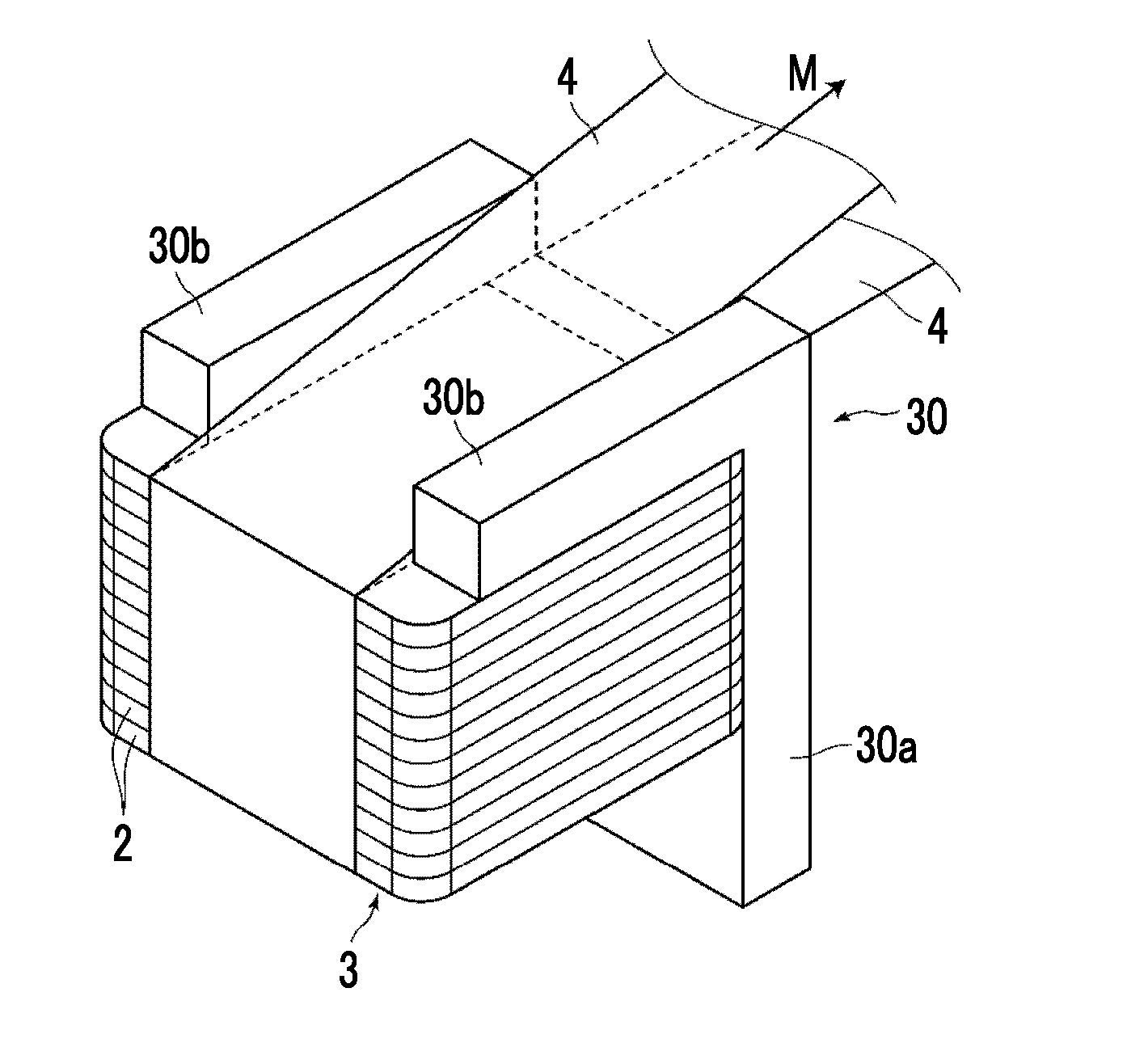
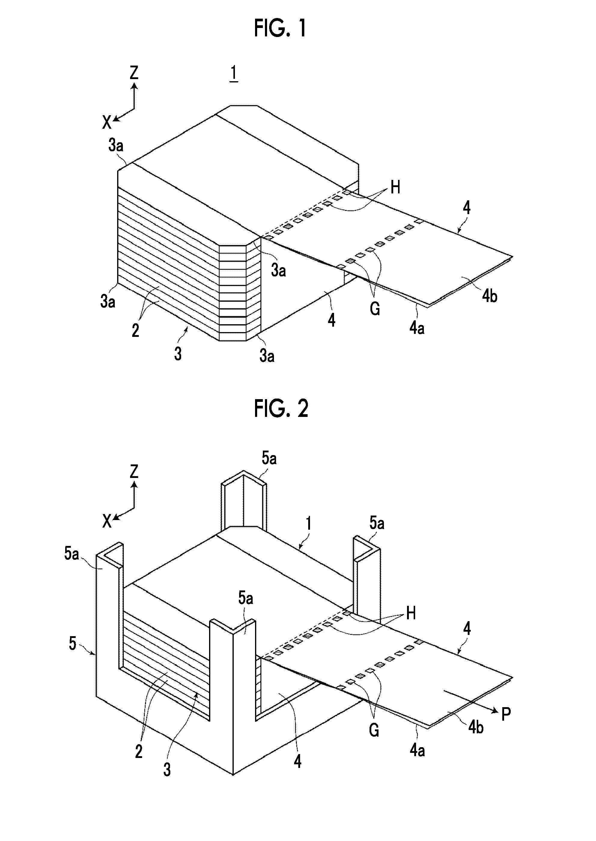
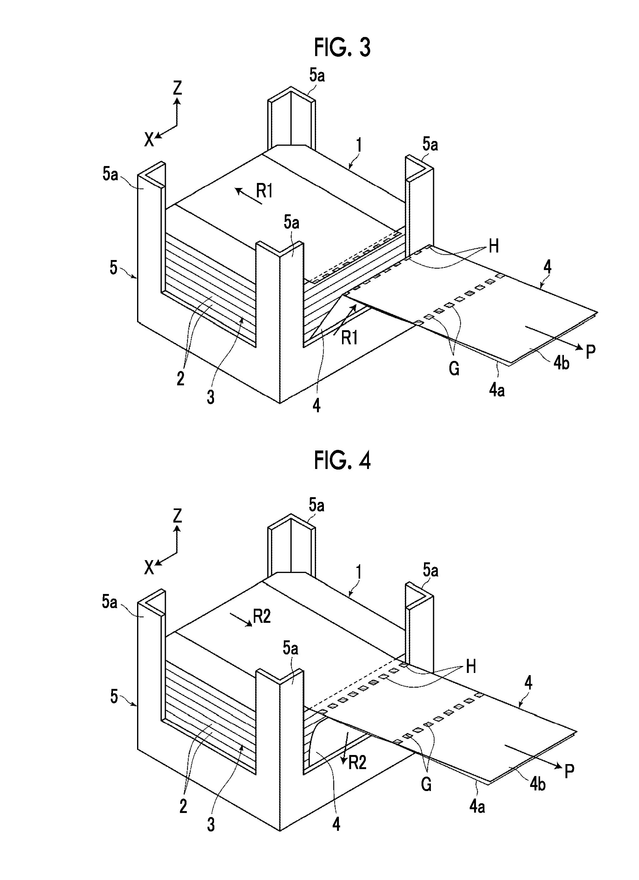
A bundled object is obtained in which a plurality of overlapped articles is sufficiently strongly bundled and it is also easy to release the bundling. A bundled object 1 is configured to include a body-to-be-bundled 3 which is made by overlapping a plurality of articles 2 and has four marginal portions 3a each extending a direction orthogonal to an overlapping direction, and a strip-shaped plastic tape 4 which bundles the body-to-be-bundled 3 by winding around the body-to-be-bundled 3 once so as to pass over the four marginal portions 3a. Then, both end portions 4a and 4b other than a winding portion of the plastic tape 4 are overlapped on each other at a position away from the body-to-be-bundled 3 and close to one marginal portion 3a, and the overlapped tape both end portions 4a and 4b are welded to each other at a plurality of welded portions H.

Description

CROSS REFERENCE TO RELATED APPLICATIONS[0001]This application claims priority under 35 U.S.C §119 to Japanese Patent Application No. 2013-122639, filed Jun. 11, 2013 and Japanese Patent Application No. 2014-115485, filed Jun. 4, 2014. Each of the above applications are hereby expressly incorporated by reference, in its entirety, into the present application.BACKGROUND OF THE INVENTION[0002]1. Field of the Invention[0003]The present invention relates to a bundled object that is made by bundling a body-to-be-bundled which is made by overlapping a plurality of articles, with a plastic tape.[0004]Further, the present invention relates to a bundling method and a bundling apparatus for manufacturing the bundled object as described above.[0005]2. Description of the Related Art[0006]In the past, in order to transport, store, or the like, articles having a relatively flat shape, overlapping a plurality of articles and then bundling the articles with a tape or a string has been widely perform...

Claims


Application Information

Patent Timeline
Patent Type & Authority Applications(United States)
IPC IPC(8): B65D71/02B65B13/32B65B13/04
CPCB65D71/02B65B13/32B65B13/04B65B27/083
Inventor AYA, SHINICHI
Owner FUJIFILM CORP
Why Eureka
Try Eureka