

Filter with a replaceable filter insert
a filter insert and replaceable technology, applied in the field of filters, can solve the problems of cost-efficient production costs and achieve the effect of high functional reliability and simple design
- Summary
- Abstract
- Description
- Claims
- Application Information
AI Technical Summary
Benefits of technology
Problems solved by technology
Method used
Image

Examples
first embodiment
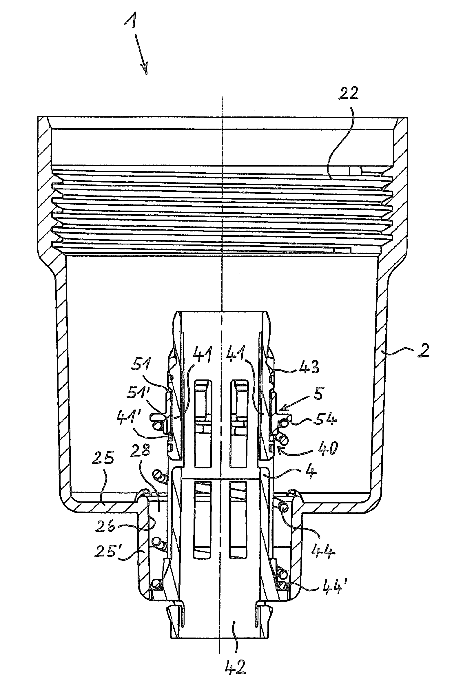
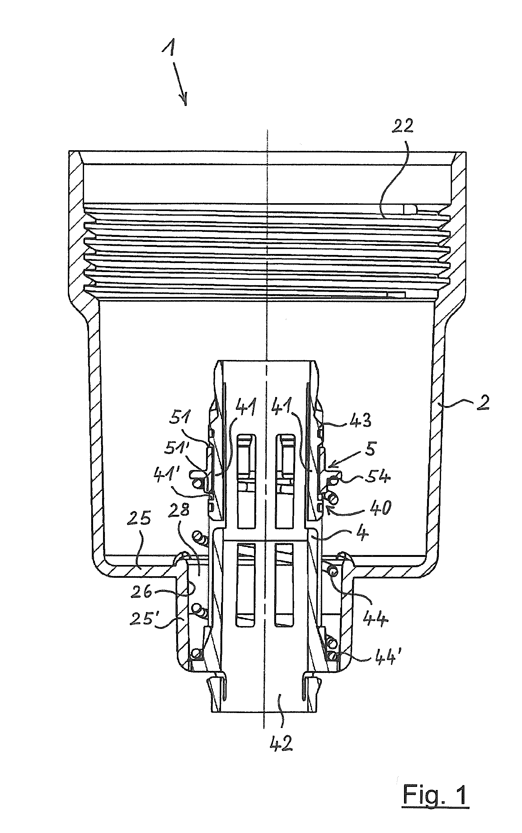
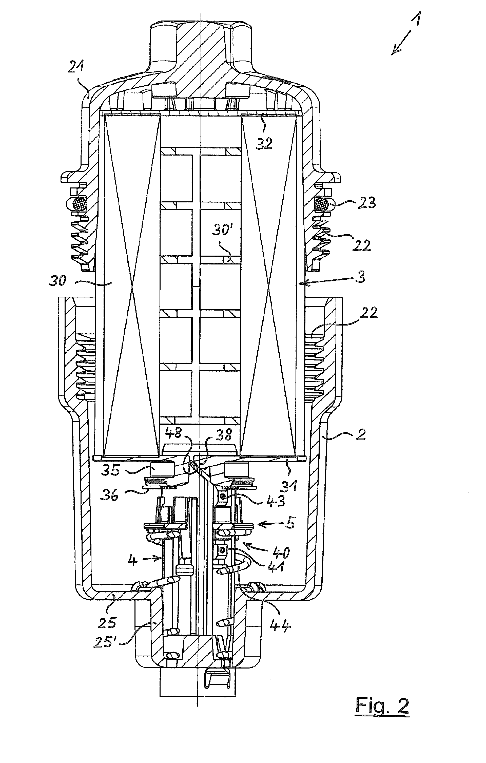
[0060]FIG. 1 shows a filter 1 in a first embodiment, comprising an open filter housing 2 and without filter insert, in longitudinal section. The filter housing 2 is cup-shaped with a bottom 25, in the center of which a hollow-cylindrical bottom part 25′, which continues downwards, is located. The inner periphery of this bottom part 25′ forms a sealing surface 26 for a seal 36 of a filter insert 3, which is not yet fitted here. On its upper end, the housing 2 has a thread 22 for being screwed to a cover 21, which is removed here. A stand pipe 4, the lower end of which is connected to the filter housing 2 and which extends upwards from that location until approximately half of the height of the filter housing 2, is arranged centrally in the interior of the filter housing 2.
[0061]A locking ring 5 is displaceably guided on the stand pipe 4 so as to be defined in axial direction. In its pushed-out direction, which faces upwards, the locking ring 5 is prestressed by the force of a spring ...
second embodiment
[0073]FIG. 8 shows a filter 1 in a second embodiment in a longitudinal section through the lower area of the filter 1, here still without filter insert. On the outside, a part of the filter housing 2 comprising the bottom 25 can be seen. The hollow-cylindrical bottom part 25′, the inner periphery of which forms the sealing surface 26, is located in the center of the bottom 25.
[0074]The stand pipe 4 is arranged in the center of the housing 2. The locking ring 5 is arranged so as to be displaceable in axial direction on the stand pipe 4. Here, the locking ring 5 can additionally also be twisted to a limited extent in peripheral direction relative to the stand pipe 4. The locking ring 5 is also prestresed here with a force, which acts in the pushed-out direction thereof, that is, upwards according to FIG. 8, and which is also created here by means of a helical spring 44. Due to the fact that a filter insert has not yet been inserted into the housing 2 in FIG. 8, the spring 44 ensures t...
third embodiment
[0086]FIGS. 15 to 24 show the filter1 in a third embodiment, for which it is characteristic that the filter housing 2 additionally encompasses a discharge channel 27, which is arranged in an eccentric position on the bottom 25 of the housing 2. The discharge channel 27 serves the purpose of releasing a path for draining liquid from the filter housing 2 when the filter insert 3 is pulled out, so that a filter insert 3, which is free from liquid as much as possible, can be removed from the filter housing 2. It is necessary thereby that the discharge channel 27 is closed during the operation of the filter 1.
[0087]FIG. 15 shows the filter 1 in the third embodiment in a longitudinal section through the lower area of the filter 1, comprising an only partially inserted filter insert 3 in longitudinal section. The cup-shaped filter housing 2 with the bottom 25 and the hollow-cylindrical bottom part 25′ thereof again forms the outer limitation of the filter insert 1. A stand pipe 4, which is...
PUM
| Property | Measurement | Unit |
|---|---|---|
| force | aaaaa | aaaaa |
| axial distance | aaaaa | aaaaa |
| distance | aaaaa | aaaaa |
Abstract
Description
Claims
Application Information