Latch Mechanism for a Fuser Assembly Having a Heat Transfer Roll

a fuser assembly and latch mechanism technology, applied in the direction of electrographic process equipment, optics, instruments, etc., can solve the problems of fuser not touching the media sheet to overheat, the fuser assembly is small and the process speed of the imaging device is decreased

Active Publication Date: 2014-12-18
LEXMARK INT INC
View PDF2 Cites 21 Cited by
  • Summary
  • Abstract
  • Description
  • Claims
  • Application Information

AI Technical Summary

Benefits of technology

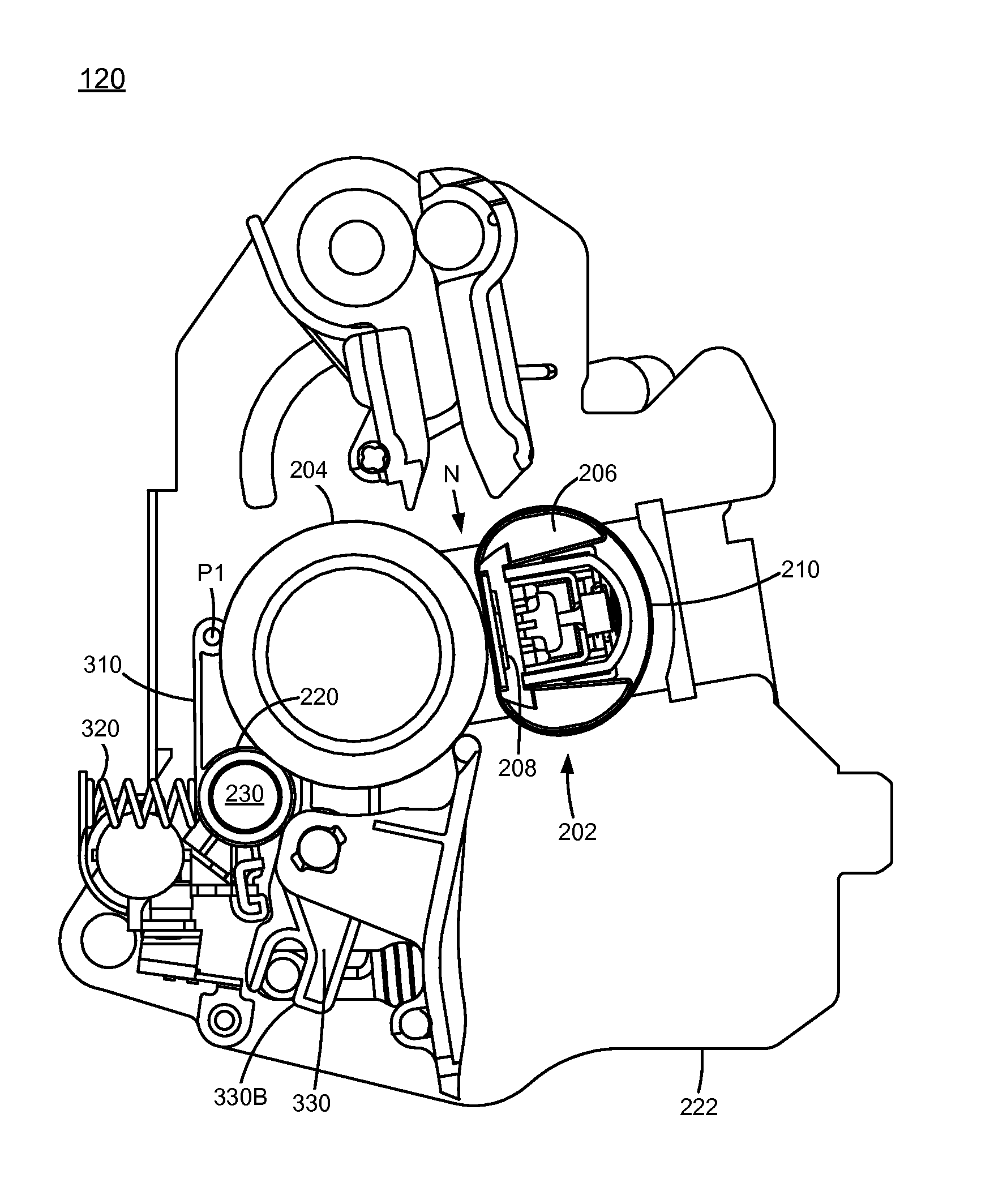
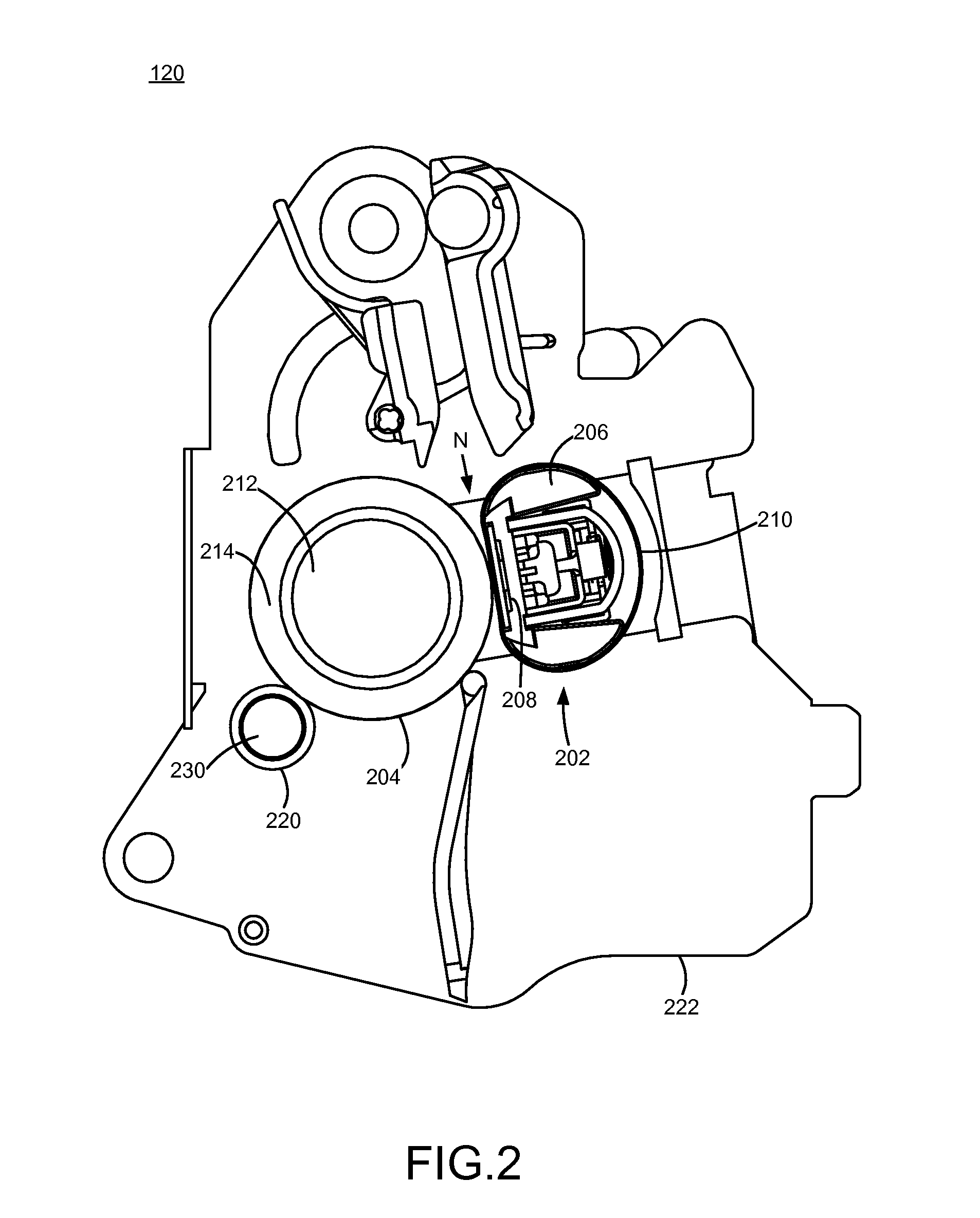
[0014]In an example embodiment, the positioning mechanism includes a crossbar member, and the latch mechanism includes a first member having a substantially sloped surface for contacting the crossbar member when the heat transfer device is moved towards the second position, and a ledge for contacting the crossbar member for latching thereof, the first member rotating relative to the housing to release the crossbar member from being latched therewith. The latch mechanism further includes a second member pivotably coupled to the housing and the first member, the second member rotating with the first member to release the crossbar member from being latched thereto. The latch mechanism may further include an actuator coupled to the housing and having a plunger, the plunger being selectively coupled to the second member such that the second member is prevented from rotational movement when coupled to the plunger.

Problems solved by technology

Typically, the inter-page gap between successive media sheets being printed is increased when media sheets less than the full width are used, thereby decreasing the process speed of the imaging device.
In the case of imaging devices operating at 60 pages per minute (ppm) and above, a media width difference of 3 mm to 4 mm is seen to cause overheating in the small portion of the fuser assembly which does not contact the media sheet.
For example, because letter paper and A4 paper differ in width by 6 mm, with A4 paper being narrower, an imaging device designed for printing on letter width media sheets and operating at 60 ppm or greater is seen to cause the portion of the fuser not contacting the media sheet to overheat if A4 paper is used, with the result that a letter width imaging device will necessarily slow when printing A4.
However, problems occur if the fuser mechanism selected for a print job does not match the media sheet width.
If the fuser mechanism associated with letter width printing is used for a print job using A4 media sheets, the fuser assembly may overheat as explained above.
Conversely, if the fuser mechanism associated with A4 width printing is used for a print job using letter width media, the toner on the outermost 6 mm (for a edge referenced imaging device) of the printed area is not sufficiently fused to the letter width media sheet.

Method used


Image

  • Latch Mechanism for a Fuser Assembly Having a Heat Transfer Roll
  • Latch Mechanism for a Fuser Assembly Having a Heat Transfer Roll
  • Latch Mechanism for a Fuser Assembly Having a Heat Transfer Roll

Examples


Embodiment Construction

[0027]It is to be understood that the present disclosure is not limited in its application to the details of construction and the arrangement of components set forth in the following description or illustrated in the drawings. The present disclosure is capable of other embodiments and of being practiced or of being carried out in various ways. Also, it is to be understood that the phraseology and terminology used herein is for the purpose of description and should not be regarded as limiting. The use of “including,”“comprising,” or “having” and variations thereof herein is meant to encompass the items listed thereafter and equivalents thereof as well as additional items. Unless limited otherwise, the terms “connected,”“coupled,” and “mounted,” and variations thereof herein are used broadly and encompass direct and indirect connections, couplings, and positionings. In addition, the terms “connected” and “coupled” and variations thereof are not restricted to physical or mechanical con...


PUM


Abstract

A fuser assembly for an electrophotographic imaging device which transfers heat from overheated portions of the fuser assembly to portions having lesser temperatures. The fuser assembly includes a heating member; a backup roll disposed proximate to the heating member so as to form a fuser nip therewith; a heat transfer device in contact with backup roll; a positioning mechanism coupled to the heat transfer device for positioning the heat transfer device in a first position in which the heat transfer device contacts the backup roll, and a second position in which the heat transfer device is spaced apart from the backup roll; and a latch mechanism for latching the heat transfer device in the second position.

Description

CROSS REFERENCES TO RELATED APPLICATIONS[0001]The present application is related to U.S. provisional application No. 61 / 834,869, filed Jun. 13, 2013, entitled, “Heat Transfer System for a Fuser Assembly,” the content of which is hereby incorporated by reference herein in its entirety.STATEMENT REGARDING FEDERALLY SPONSORED RESEARCH OR DEVELOPMENT[0002]None.REFERENCE TO SEQUENTIAL LISTING, ETC.[0003]None.BACKGROUND[0004]1. Field of the Disclosure[0005]The present disclosure relates generally to a fuser assembly for an electrophotographic imaging device and particularly to a fuser assembly which transfers excess heat from one location to another location in the fuser assembly.[0006]2. Description of the Related Art[0007]In a belt fuser assembly for an electrophotographic imaging device, an endless belt surrounds a ceramic heating element. The belt is pushed against the heating element by a pressure roller to create the fusing nip. The heating element, typically a thick-film resistor o...

Claims


Application Information

Patent Timeline
Patent Type & Authority Applications(United States)
IPC IPC(8): G03G15/20
CPCG03G15/2028G03G15/2064G03G2215/2035G03G15/2046G03G15/2042G03G15/2032G03G15/2053G03G21/1647G03G21/1685
Inventor BAYERLE, PETER ALDENBUCHANAN, JEFFERY JAMES
Owner LEXMARK INT INC
Why Eureka
Try Eureka