Elastic retaining assembly for matable components and method of assembling

a technology of elastic retaining assembly and matable components, applied in the field of matable components, can solve the problems of poor fit, undesirable effects, poor perceived quality,

Inactive Publication Date: 2014-12-18
GM GLOBAL TECH OPERATIONS LLC
View PDF11 Cites 21 Cited by
  • Summary
  • Abstract
  • Description
  • Claims
  • Application Information

AI Technical Summary

Problems solved by technology

As a result, occurrence of significant positional variation between the mated components is possible, which contributes to the presence of undesirably large and varying gaps and otherwise poor fit.
The clearance between the a...

Method used


Image

  • Elastic retaining assembly for matable components and method of assembling
  • Elastic retaining assembly for matable components and method of assembling
  • Elastic retaining assembly for matable components and method of assembling

Examples


Embodiment Construction

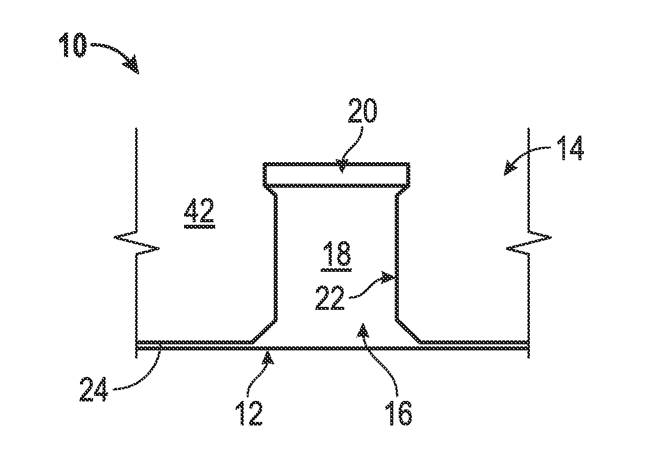
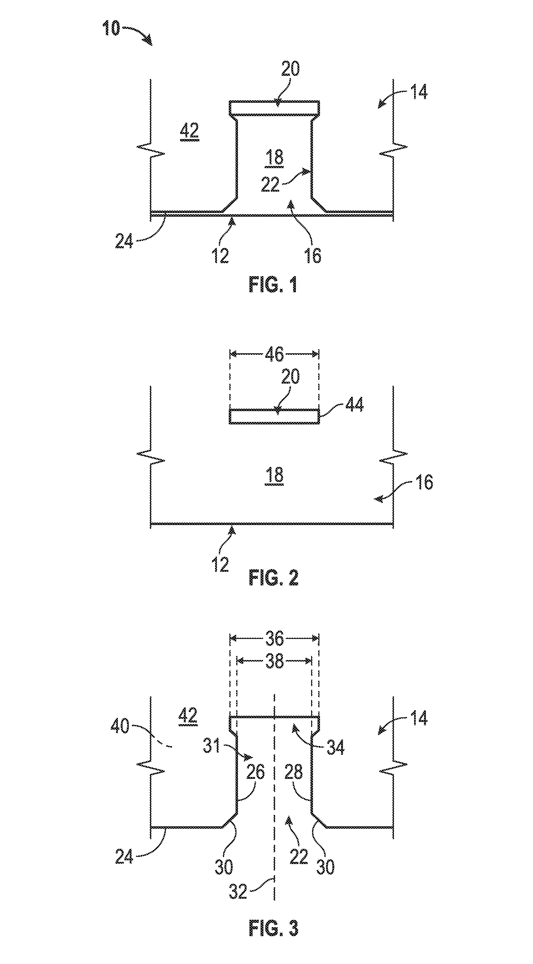
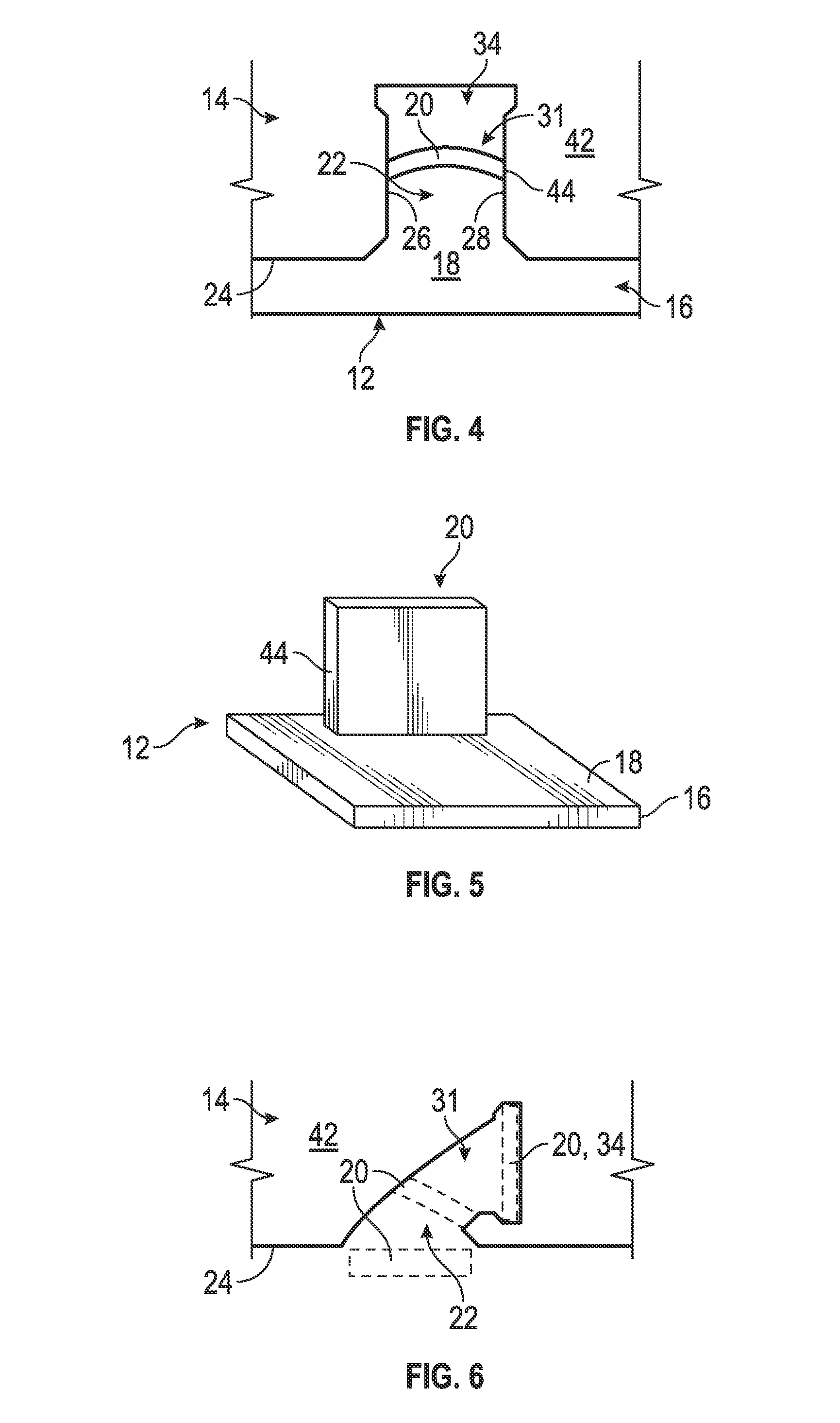
[0017]Referring to FIGS. 1-3, an elastic retaining assembly 10 is illustrated. The elastic retaining assembly 10 comprises matable components, such as a first component 12 and a second component 14 that are configured to be mated and aligned with respect to each other. In one embodiment, the elastic retaining assembly 10 is employed in a vehicle application. However, it is to be understood that the components may be associated with numerous other applications and industries, such as home appliance and aerospace applications, for example. In an exemplary embodiment such as the aforementioned vehicle application, the first component 12 comprises an automotive air deflector and the second component 14 comprises an automotive fascia.

[0018]Although illustrated in a specific geometry, the first component 12 and the second component 14 may be configured in countless geometries. Regardless of the precise geometry of the first component 12 and the second component 14, the first component 12 ...


PUM

PropertyMeasurementUnit
Widthaaaaaaaaaa
Elasticityaaaaaaaaaa
Deformation enthalpyaaaaaaaaaa

Abstract

An elastic retaining assembly for matable components includes a first component having a first surface. Also included is a second component configured to be mated with the first component, the second component comprising a second surface. Further included is a receiving feature formed proximate an engagement side of the second component, the receiving feature having a first degree of curvature. Yet further included is an elastically deformable protrusion operatively coupled to, and extending away from, the first component, the elastically deformable protrusion having a second degree of curvature distinct from the first degree of curvature of the receiving feature, wherein the elastically deformable protrusion is formed of an elastically deformable material and configured to elastically deform upon engagement with the receiving feature.

Description

FIELD OF THE INVENTION[0001]The invention relates to matable components and, more particularly, to an elastic retaining assembly for such matable components, as well as a method of assembling the matable components.BACKGROUND[0002]Currently, components which are to be mated together in a manufacturing process are subject to positional variation based on the mating arrangements between the components. One common arrangement includes components mutually located with respect to each other by 2-way and / or 4-way male alignment features; typically undersized structures which are received into corresponding oversized female alignment features such as apertures in the form of openings and / or slots. Alternatively, double-sided tape, adhesives or welding processes may be employed to mate parts. Irrespective of the precise mating arrangement, there is a clearance between at least a portion of the alignment features which is predetermined to match anticipated size and positional variation toler...

Claims


Application Information

Patent Timeline
IPC IPC(8): F16B17/00
CPCF16B17/002F16B3/00F16B5/0012F16B5/0614F16B21/088Y10T29/4987Y10T403/4949F16B17/00
Inventor MORRIS, STEVEN E.LAWALL, JENNIFER P.
Owner GM GLOBAL TECH OPERATIONS LLC
Why Eureka
Try Eureka