Joint assembly and method of forming thereof

a technology of joint assembly and forming method, which is applied in the direction of couplings, machines/engines, manufacturing tools, etc., can solve the problems of labor-intensive and costly process of ndi, and achieve the effect of facilitating the restriction of the movement of the tip

Active Publication Date: 2014-12-25
THE BOEING CO
View PDF37 Cites 7 Cited by
  • Summary
  • Abstract
  • Description
  • Claims
  • Application Information

AI Technical Summary

Benefits of technology

[0007]In another aspect, a spar assembly for use in a rotary blade system is provided. The assembly includes a body extending from a root portion to a tip portion and the body is formed from a first material. The assembly also includes a tip fitting including a portion that extends at least partially into the tip portion and that has an uneven outer profile. The first material is configured to form the body into a shape that is substantially complementary to a shape of the portion to facilitate restricting movement of the tip fitting in an axial direction.

Problems solved by technology

However, NDI may be a labor-intensive and costly process.

Method used


Image

  • Joint assembly and method of forming thereof
  • Joint assembly and method of forming thereof
  • Joint assembly and method of forming thereof

Examples


Embodiment Construction

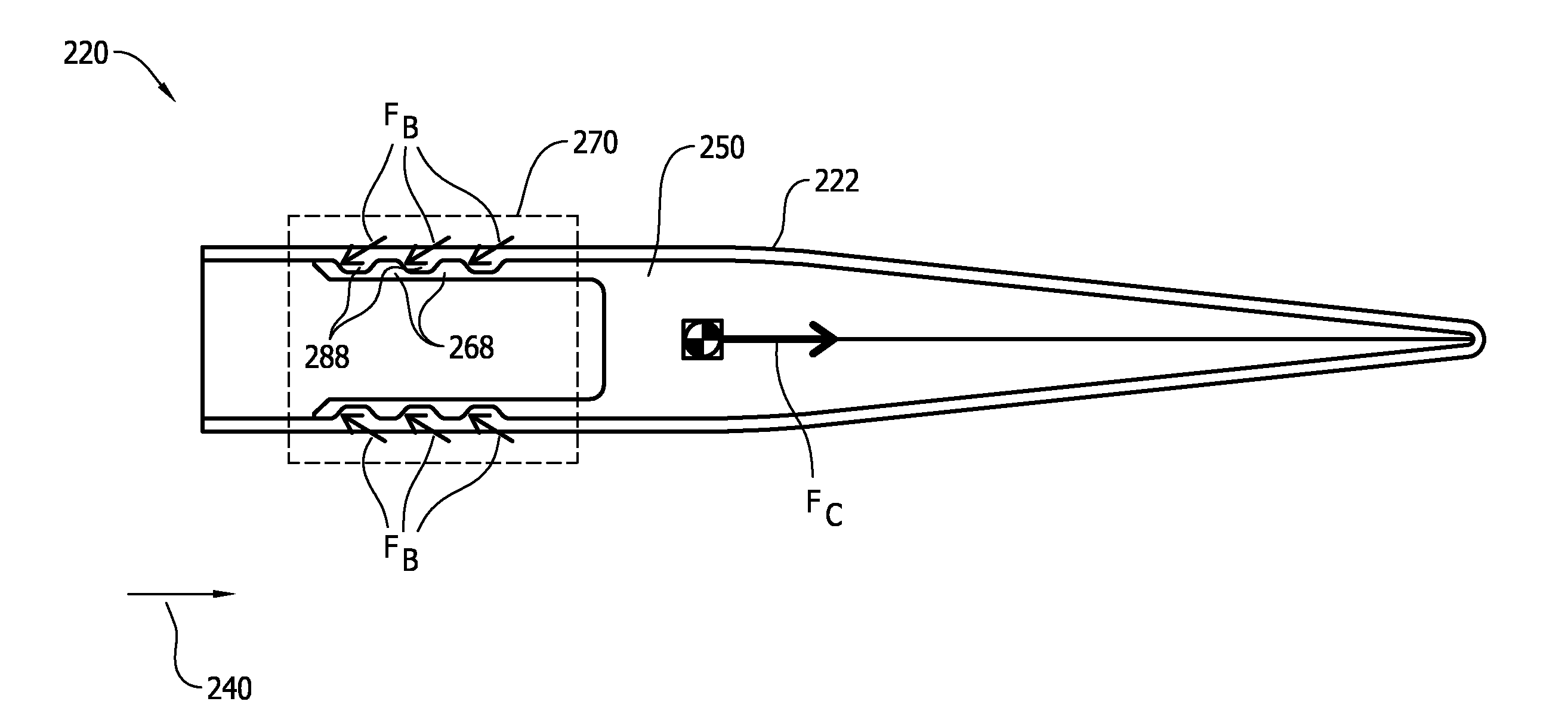
[0017]The implementations described herein relate to assemblies and methods that facilitate restricting axial movement between components of a joint assembly. In the exemplary implementation, the joint assembly includes a first component and a second component that include each features that interlock to facilitate forming a mechanical joint. More specifically, a portion of the first component that is at least partially insertable into the second component has an uneven outer profile, and the second component is formed from a material that conforms to a shape of the uneven outer profile. As such, the mechanical joint is formed between the first component and the second component that facilitates restricting axial movement between the components without the use of a film adhesive.

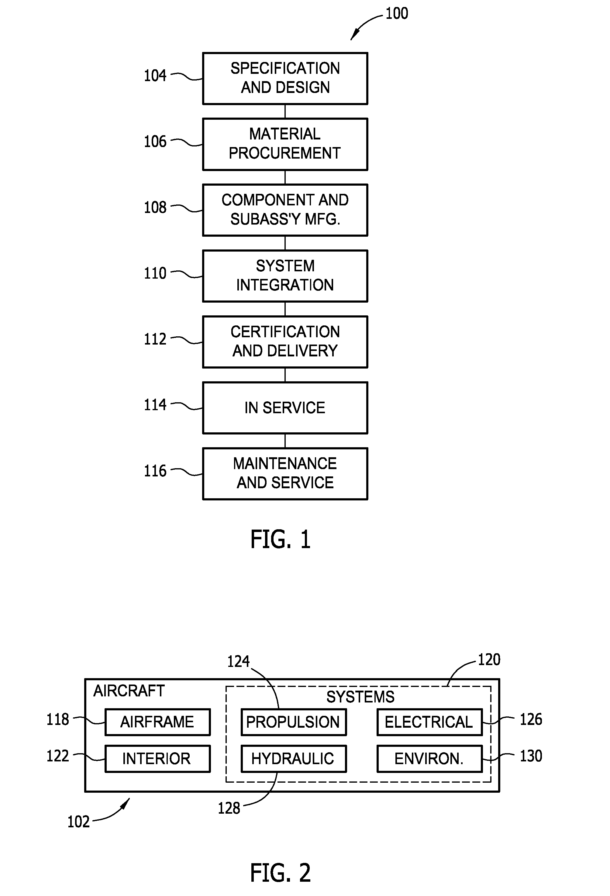
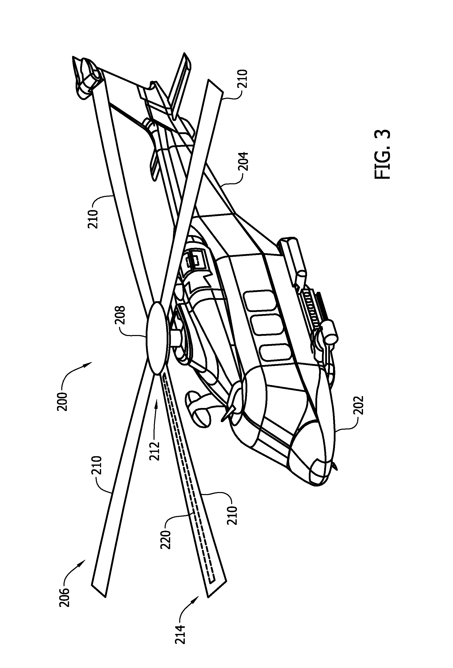
[0018]Referring to the drawings, implementations of the disclosure may be described in the context of an aircraft manufacturing and service method 100 (shown in FIG. 1) and via an aircraft 102 (shown in FIG....


PUM

PropertyMeasurementUnit
shapeaaaaaaaaaa
thicknessaaaaaaaaaa
metallicaaaaaaaaaa

Abstract

A joint assembly is provided. The joint assembly includes a first component formed from a first material and a second component including a portion that extends at least partially into the first component and that has an uneven outer profile. The first material is configured to form the first component into a shape that is substantially complementary to a shape of the portion to facilitate restricting movement of the second component in an axial direction.

Description

STATEMENT REGARDING FEDERALLY SPONSORED RESEARCH & DEVELOPMENT[0001]This invention was made with Government support under Contract No. W911W6-07-D 0002-0020 ITRB Phase IV(EATTS TO 20) awarded by the Army. The Government has certain rights in this invention.BACKGROUND[0002]The field of the present disclosure relates generally to joint assemblies and, more specifically, to a mechanical joint that facilitates restricting movement between components thereof[0003]Recently, at least some known aircraft components have been fabricated from multi-layer laminate structures of non-metallic composite materials such as carbon-fiber-reinforced polymer (CFRP). The composite materials may be used in combination with metallic materials, such as aluminum, titanium, and / or steel, to reduce the weight of the aircraft. As used herein, the term “metallic” may refer to a single metallic material or a metallic alloy material. Reducing overall weight generally contributes to increasing the fuel efficiency ...

Claims


Application Information

Patent Timeline
Patent Type & Authority Applications(United States)
IPC IPC(8): B64C11/26F16B11/00
CPCF16B11/002B64C11/26B64C27/473B64C2027/4736Y10T29/49337Y10T403/4966
Inventor KENNEDY, DENNIS K.STAHLECKER, ZACH K.OPIE, SAUL
Owner THE BOEING CO
Why Eureka
Try Eureka