
Electronic detonator

a technology of detonators and detonators, which is applied in the direction of ammunition fuzes, blasting cartridges, weapons components, etc., can solve the problems of limited electrical energy produced by the generator, limited use, and limiting the duration of the time delay interval to about 3 seconds, so as to reduce the loss of eddy curren

Active Publication Date: 2015-01-15
DETNET SOUTH AFRICA (PTY) LTD
View PDF11 Cites 8 Cited by
  • Summary
  • Abstract
  • Description
  • Claims
  • Application Information

AI Technical Summary

Benefits of technology

This patent describes an invention that allows a magnet to move freely through a passage using a cobustible adhesive. The adhesive helps to hold the magnet in position when it is not moving, but when the magnet needs to move, the adhesive reduces its strength, allowing the magnet to move without any resistance. This reduces energy loss and allows the magnet to move at a high speed. The patent also mentions the use of a lubricant to ensure smooth movement of the magnet, the use of a low-frequency electrical signal to avoid eddy current losses, and the importance of the duration and magnitude of the pressure pulse and the number of windings in the coil. The patent also suggests using an active bridge to decrease losses and improve efficiency. Overall, this invention allows for smoother and more efficient movement of the magnet through the passage.

Problems solved by technology

Although the aforementioned detonators do away with the need for interconnecting conductive wires, their usage is limited in one respect namely that each detonator is programmed under factory conditions with a predetermined delay time.
Another drawback which is linked to a detonator which makes use of a magnetic generator is that the quantity of electrical energy which is produced by the generator may be limited and this would restrict the duration of the time delay interval to about 3 seconds (in the case of the ISKRA-T).
A detonator which has an on-board battery, as a power source, inherently has a limited shelf life.
By way of contrast magnetically and piezo-powered detonators do not have a battery-imposed shelf life limitation but, as noted, are not normally capable of executing a long time delay.

Method used


Image

  • Electronic detonator
  • Electronic detonator
  • Electronic detonator

Examples


Embodiment Construction

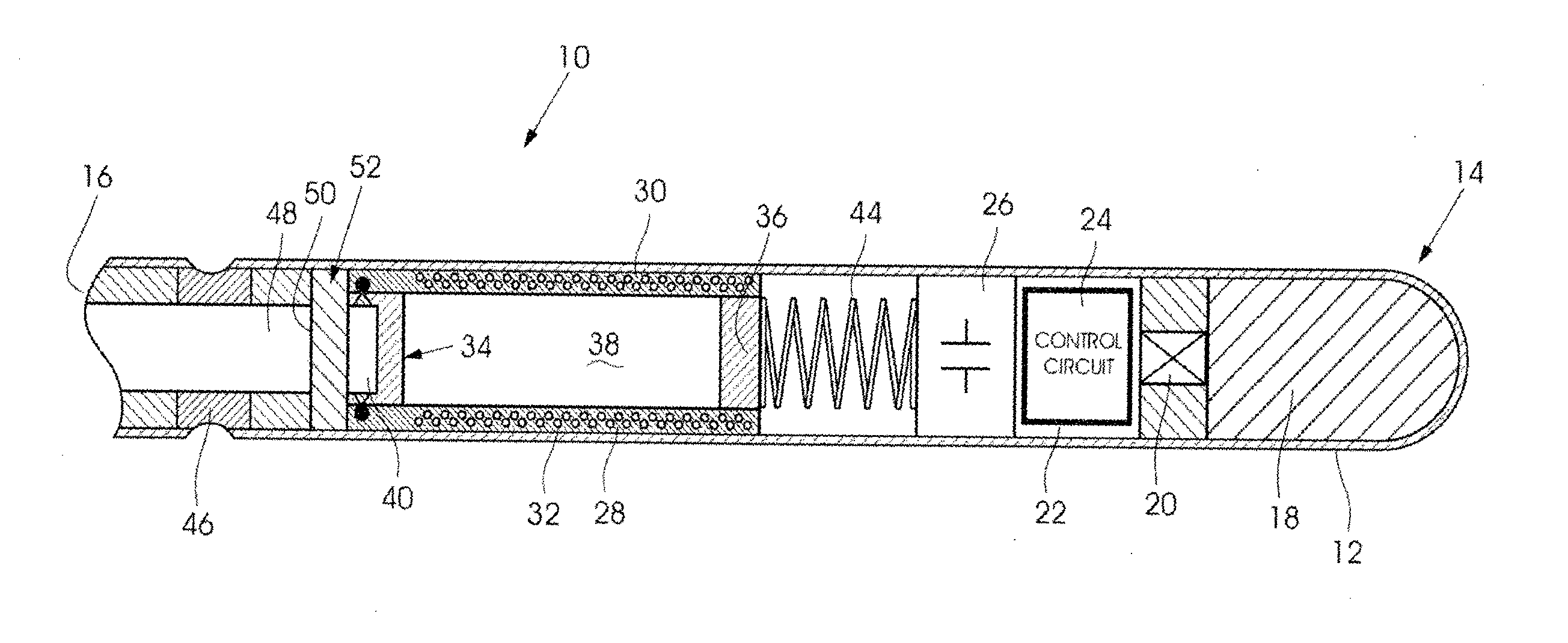
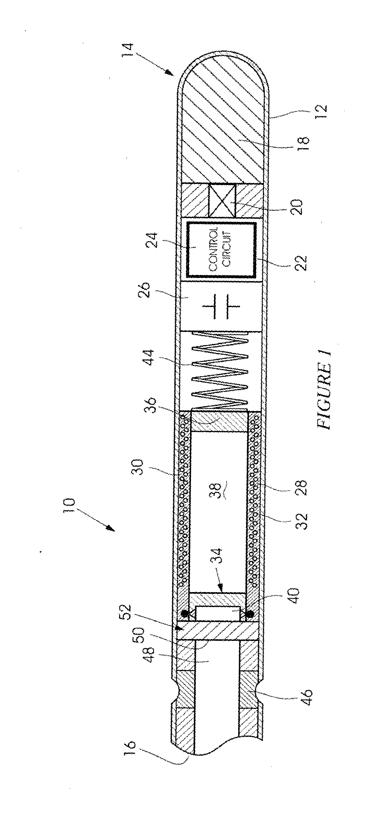
[0042]FIG. 1 of the accompanying drawings illustrates in cross-section and from one side an electronic detonator 10 according to the invention. The detonator includes a metallic tubular housing 12 made for example from aluminium or copper which has a blind end 14 and a mouth 16. An explosive charge 18 of a kind known in the art is loaded into the tubular housing and is exposed to an initiating element 20 which is carried on a printed circuit board 22. This board carries a control unit or processor 24 and includes an energy storage arrangement 26 comprising, for example one or more capacitors. The construction of the detonator described thus far is largely conventional and for this reason is not elaborated on.

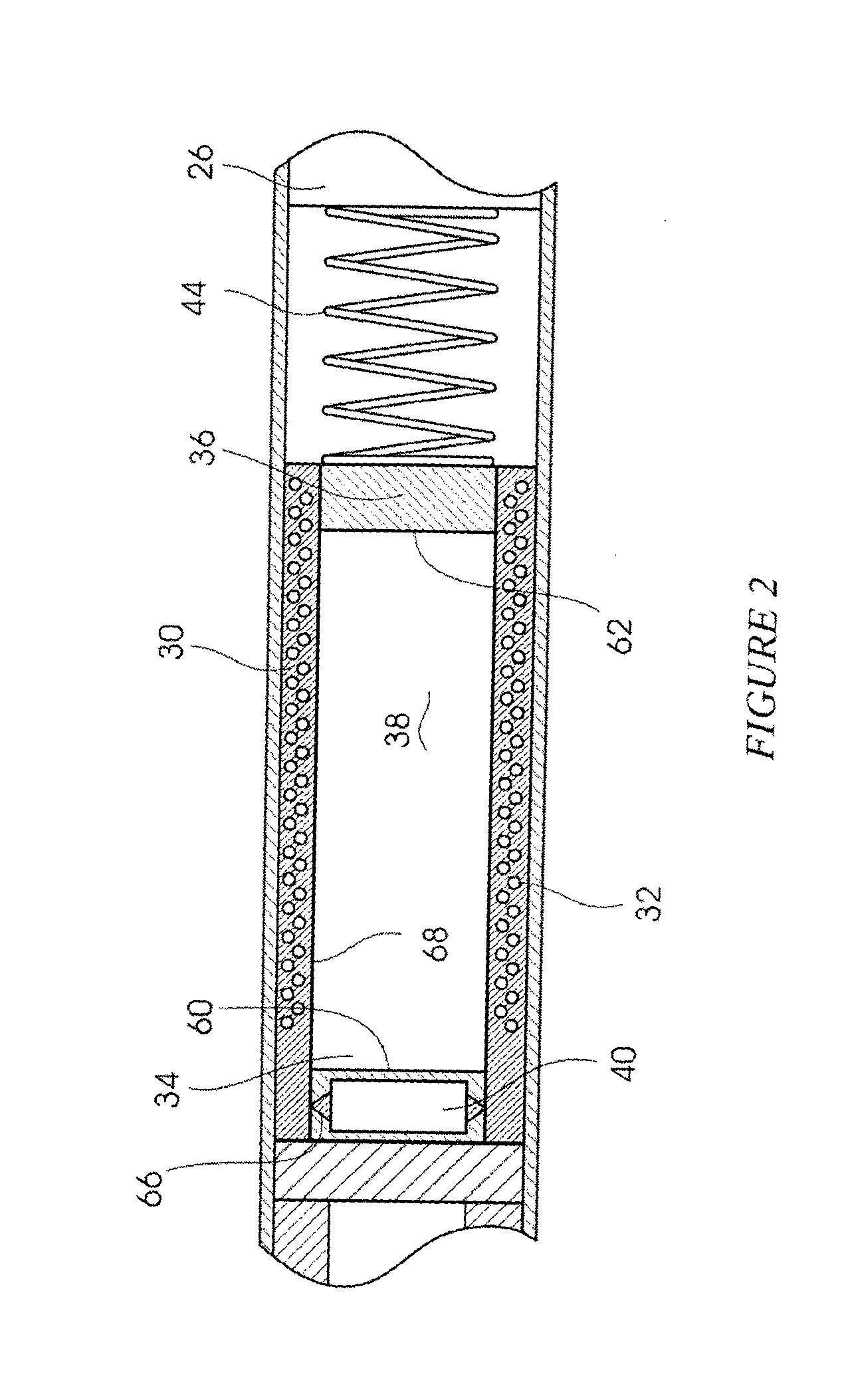
[0043]A tube 28 is positioned in the housing 12 fairly close to the mouth 16. The tube is made from a suitable insulating material and, embedded in the tube, are a plurality of windings 30 which constitute an elongate coil 32. The coil 32 has a first end 34, a second remote end ...


PUM


Abstract

An electronic detonator (10) which includes a housing (12) which contains an explosive charge (18), an initiating element (20), a control circuit (24), at least one coil (32) having a plurality of windings (30) in a tubular configuration, and a magnet (40) wherein passage of the magnet (40) through the coil (32) creates voltage to which the control circuit (24) is responsive, and a connector (46) for connecting a shock tube (48) to the housing (12).

Description

BACKGROUND OF THE INVENTION[0001]This invention relates to an electronic detonator.[0002]An electronic detonator typically includes a timer which is capable of executing a time delay with a degree of accuracy which is not attainable with a pyrotechnic device. This allows for improved blasting and fragmentation of rock.[0003]Various techniques exist for initiating an electronic detonator. In one approach an end of a shock tube is exposed to one or more sensors which are included in a detonator. These sensors, in response to a genuine shock tube event, commence a process for initiating the detonator. A benefit which is associated with the use of a shock tube to initiate a detonator, is that some of the problems associated with traditional wired electronic blasting systems, such as wire breakage or current leakage in harsh environments, are obviated.[0004]One kind of shock tube-initiated, electronic detonator employs a piezoelectric element which, in response to a pressure wave produce...

Claims


Application Information

Patent Timeline
IPC IPC(8): F42B3/10
CPCF42B3/10F42B3/122F42C11/008F42C11/04F42D1/043
Inventor SCHLENTER, CRAIG CHARLESVAN DER WALT, HERMAN
Owner DETNET SOUTH AFRICA (PTY) LTD
Learn More