Apparatus for casting a non-pneumatic tire having a floating mold alignment mechanism

a technology of rotating molds and tires, which is applied in the direction of dough shaping, manufacturing tools, food shaping, etc., can solve the problems of undesirable and non-uniform appearance, prone to stick of spokes, and distortion of spokes and annular bands,

Active Publication Date: 2015-01-15
MICHELIN RECH & TECH SA +1
View PDF4 Cites 13 Cited by
  • Summary
  • Abstract
  • Description
  • Claims
  • Application Information

AI Technical Summary

Benefits of technology

The patent describes an apparatus for aligning a floating mold in a manufacturing process. The apparatus includes a mechanism that allows the mold to move in at least one direction. This mechanism includes an attachment member with a hole and a stud with threaded ends. The stud is attached to a slide and the attachment member is positioned between them. A nut is attached to the end of the stud that extends beyond the attachment member. The technical effect of this mechanism is to provide a way to adjust the movement of the mold alignment mechanism in a controlled and precise manner.

Problems solved by technology

The technical problem addressed in this patent text is the need for an apparatus and method for manufacturing non-pneumatic or hybrid tires using mold cores with undrafted surfaces and without the use of tie bars. Additionally, the apparatus should allow for adjustment or movement of the mold half in the radial direction of the tire to avoid distortion of the spokes.

Method used


Image

  • Apparatus for casting a non-pneumatic tire having a floating mold alignment mechanism
  • Apparatus for casting a non-pneumatic tire having a floating mold alignment mechanism
  • Apparatus for casting a non-pneumatic tire having a floating mold alignment mechanism

Examples


Embodiment Construction

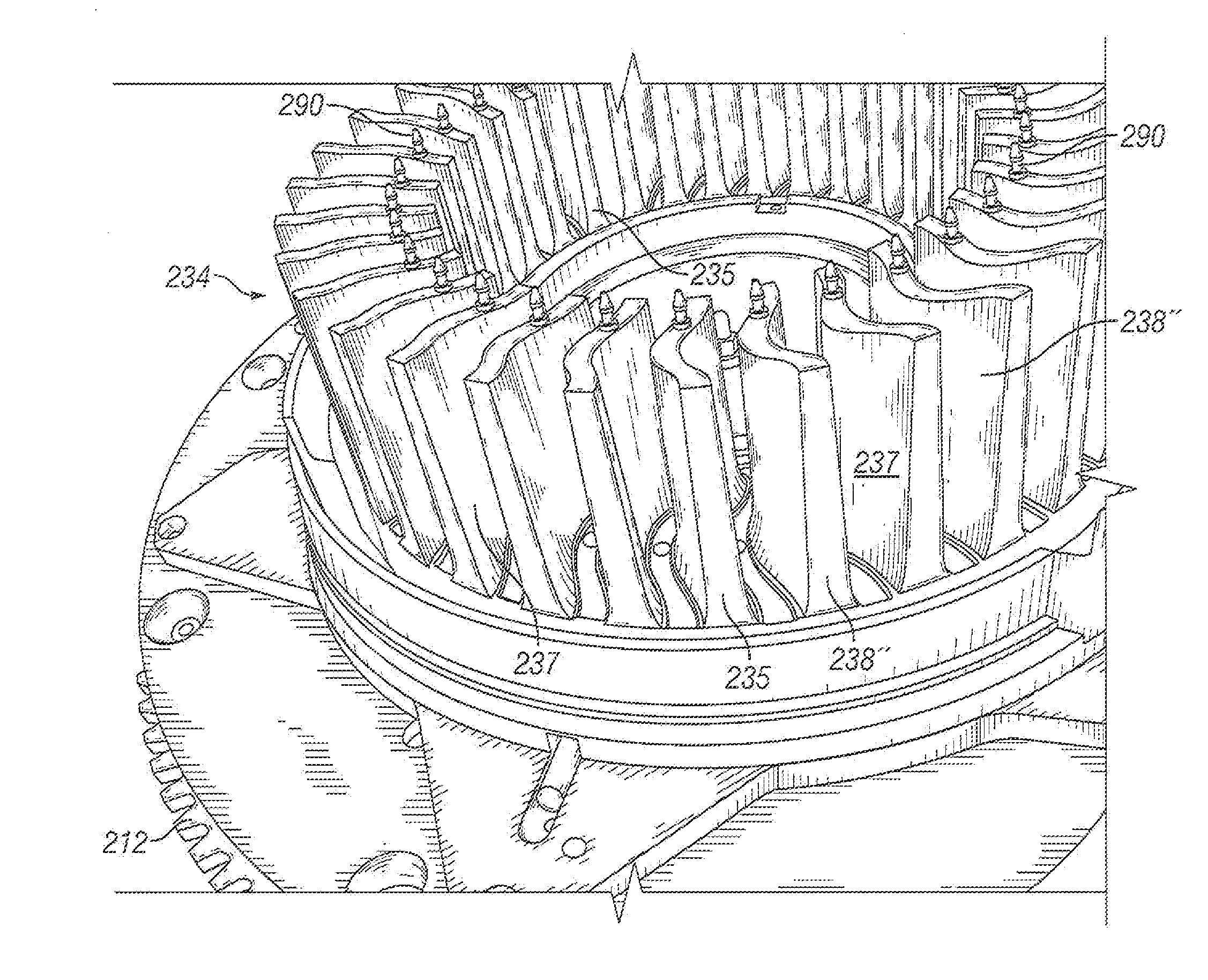
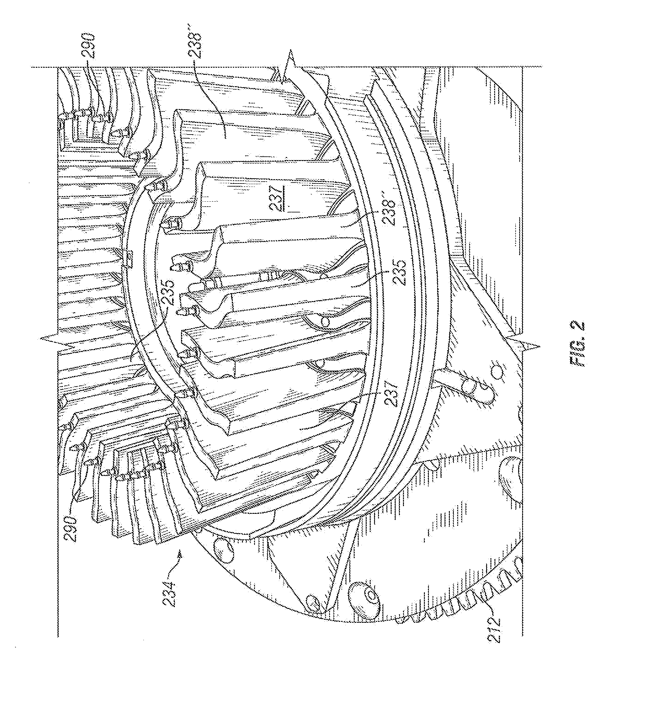
[0030]Looking at FIGS. 3 thru 3C, an apparatus 200 for molding a portion of a tire 100 in a manner consistent with one embodiment of the present invention is depicted. Specifically as best seen in FIGS. 3 and 3A, this apparatus 200 includes a vertical molding press 202 comprising a lower platen 204, upper platen 206, hydraulic cylinder 208, arm 210, a gear 212 and frame 214. The frame 214 is fixed and the lower platen 204 is translatably fixed in a horizontal plane but is free to translate vertically while the upper platen 206 is pivotally connected to the frame 214 via pin 211. The upper platen 206 is moved by the hydraulic cylinder 208 in and out of a parallel alignment with the lower platen 204. Both platens can also rotate about a horizontal axis as previously described. The gear 212 mates with a drive pinion (not shown) powered by a motor (not shown) that can engage and disengage the gear 212 when it is appropriate to rotate the lower platen 204 and mold 216, which is affixed t...


PUM

PropertyMeasurementUnit
Lengthaaaaaaaaaa

Abstract

This invention relates generally to an apparatus for rotationally casting a portion of a tire, and, more specifically, to an apparatus that has a floating alignment mechanism that allows a portion of a mold to move in the radial direction of the tire, which it, at least; partially forms, allowing the molding apparatus to omit, the use of tie bars. The mechanism may comprise two set of needle roller bearings that are orthogonally arranged to allow radial movement of a portion of a mold.

Description


Claims


Application Information

Patent Timeline
Owner MICHELIN RECH & TECH SA
Why Eureka
Try Eureka