Method and arrangement for controlling a wind turbine

a technology of wind turbines and wind power, which is applied in the direction of wind power generation, motors, engine control, etc., can solve the problems of increasing the power produced by wind turbines, increasing the wind speed, so as to improve the method and reduce the rotational speed of the rotor. , the effect of increasing the wind speed

Inactive Publication Date: 2015-01-22
SIEMENS GAMESA RENEWABLE ENERGY AS
View PDF9 Cites 19 Cited by
  • Summary
  • Abstract
  • Description
  • Claims
  • Application Information

AI Technical Summary

Benefits of technology

[0007]According to an embodiment of the present invention, it is provided a method for controlling a wind turbine having a rotor and being connected to a utility grid, the method comprising increasing a rotational speed of the rotor from a typical, in particular nominal, rotational speed to an increased rotational speed.
[0041]According to an embodiment of the present invention, it is provided an arrangement for controlling a wind turbine having a rotor and being connected to a utility grid, the arrangement comprising a processor for generating a control signal for transmission to a drive train of the wind turbine for increasing a rotational speed of the rotor from a typical, in particular nominal, rotational speed to an increased rotational speed.

Problems solved by technology

Electrical power needed by the consumers may not in all situations balance electrical power produced by the wind turbines.
In other situations, the electrical power produced by the wind turbines may be larger than the power consumed by the consumers, in which case curtailment of the power from the wind turbines may be required.
By pitching out the rotor blades, the efficiency of energy transfer from the wind to the rotor to which the rotor blades are connected may be decreased, resulting in a decrease of power output by the wind turbines.
It has been observed that stability of the utility grid may not be ensured in a sufficient manner in all conditions of wind speed, demand at the utility grid and operating conditions of the wind turbine.

Method used


Image

  • Method and arrangement for controlling a wind turbine
  • Method and arrangement for controlling a wind turbine
  • Method and arrangement for controlling a wind turbine

Examples


Embodiment Construction

[0054]The illustration in the drawings is in schematic form.

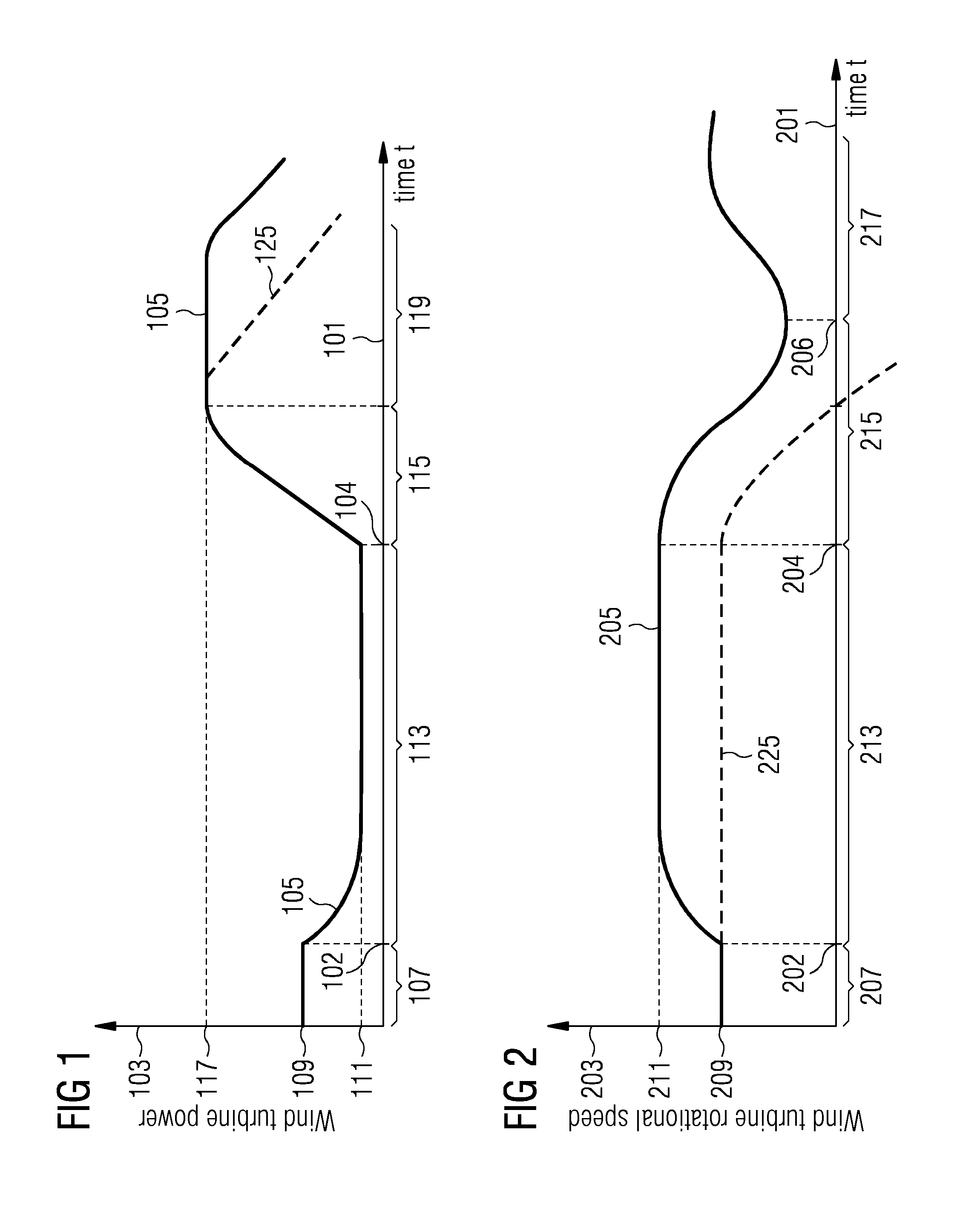
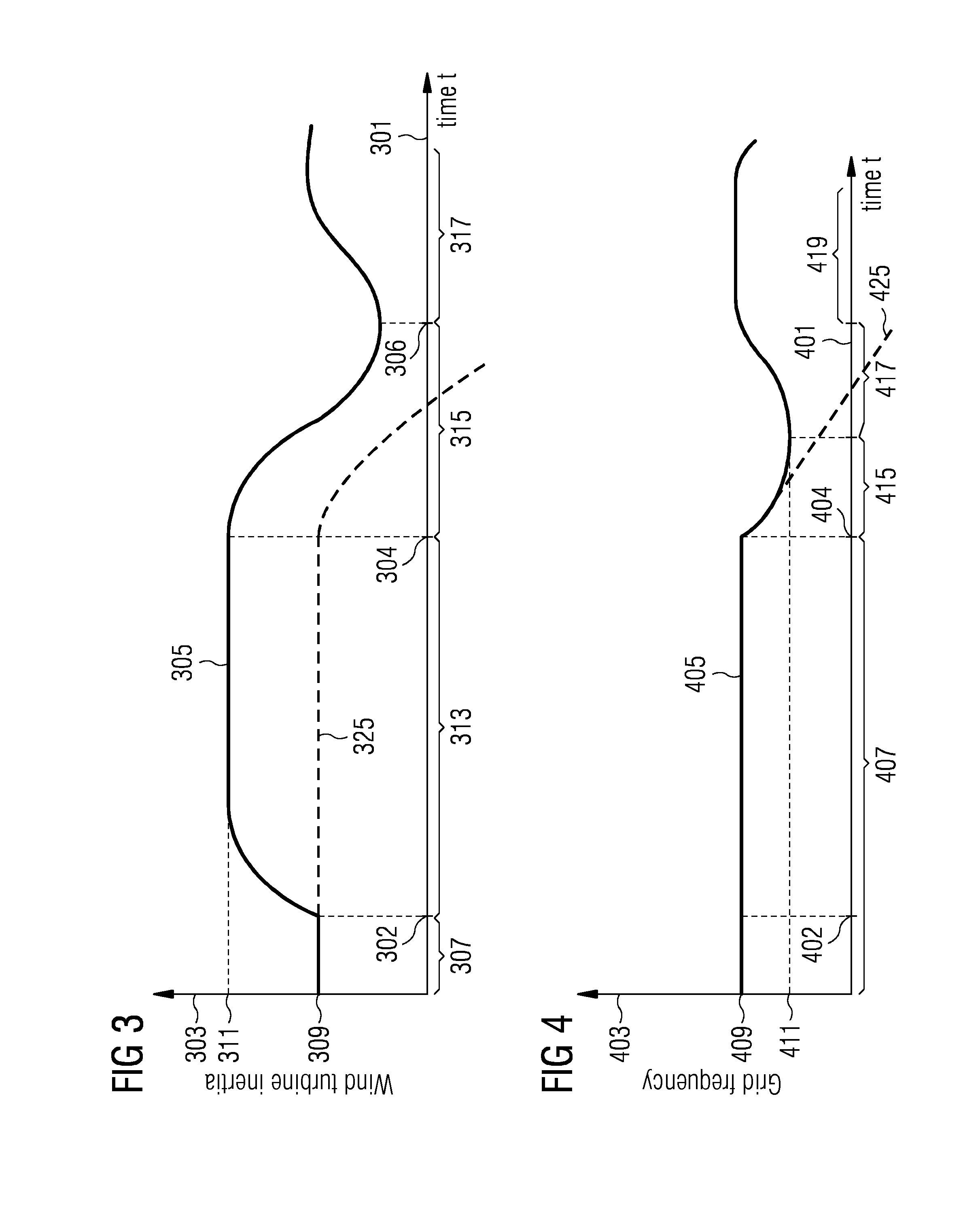
[0055]In the FIGS. 1 to 4, the abscissas 101, 201, 301 and 401 denote the time, 102 to 402, 104 to 404 denote particular time points. The ordinate 103 denotes a power output of the wind turbine (in FIG. 1), 203 denotes the rotational speed of a rotor of the wind turbine (in FIG. 2), 303 denotes the wind turbine inertia, i.e. the inertia of the rotor including the blades (FIGS. 3) and 403 denotes the grid frequency (FIG. 4) in arbitrary units. The curves 105, 205, 305, 405 in FIGS. 1-4 thereby illustrate exemplary time courses of the respective electrical / mechanical quantities as achieved in a method for controlling a wind turbine according to an embodiment of the present invention. Thereby, events at a same horizontal position in the different figures occur at the same time.

[0056]The curve 105 in FIG. 1 indicates a power output of a wind turbine in the control method according to an embodiment of the present invention. In a...


PUM


Abstract

It is described a method and an arrangement for controlling a wind turbine (811) having a rotor (813) and being connected to a utility grid (831), the method comprising: increasing a rotational speed (205) of the rotor from a typical rotational speed (209, 505) to an increased rotational speed (211, 507).

Description

FIELD OF INVENTION[0001]The present invention relates to a method and to an arrangement for controlling a wind turbine, in particular for improving a stability of a utility grid to which the wind turbine is connected.ART BACKGROUND[0002]One or more wind turbines may form a wind park which is connected to a utility grid which may provide electrical energy to plural consumers. Electrical power needed by the consumers may not in all situations balance electrical power produced by the wind turbines. In particular, if a large load is connected or switched on to the utility grid, a decrease of the frequency of the grid may be expected. In this case, the wind turbines may give only a limited inertia response, in order to support or stabilize the frequency. In other situations, the electrical power produced by the wind turbines may be larger than the power consumed by the consumers, in which case curtailment of the power from the wind turbines may be required. Thereby, in a conventional met...

Claims


Application Information

Patent Timeline
Patent Type & Authority Applications(United States)
IPC IPC(8): F03D7/02
CPCF03D7/0276F05B2270/337F03D7/0284F05B2270/1033F05B2270/1016Y02E10/72
Inventor BECH, JOHN
Owner SIEMENS GAMESA RENEWABLE ENERGY AS
Why Eureka
Try Eureka