Projector
- Summary
- Abstract
- Description
- Claims
- Application Information
AI Technical Summary
Benefits of technology
Problems solved by technology
Method used
Image

Examples
first embodiment
[0027]Referring to FIGS. 1 to 6, a projector 1 is illustrated in accordance with a first embodiment.
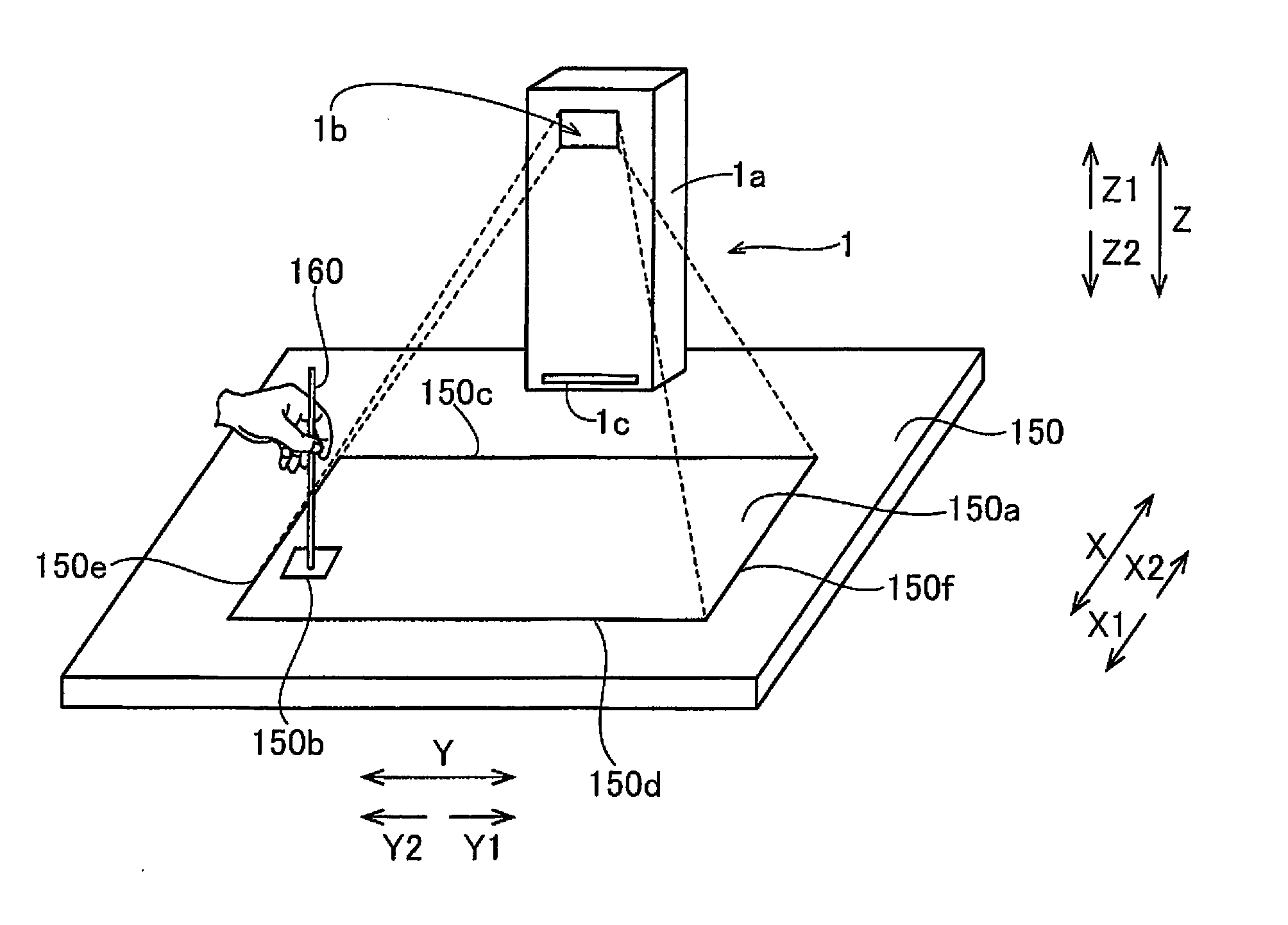
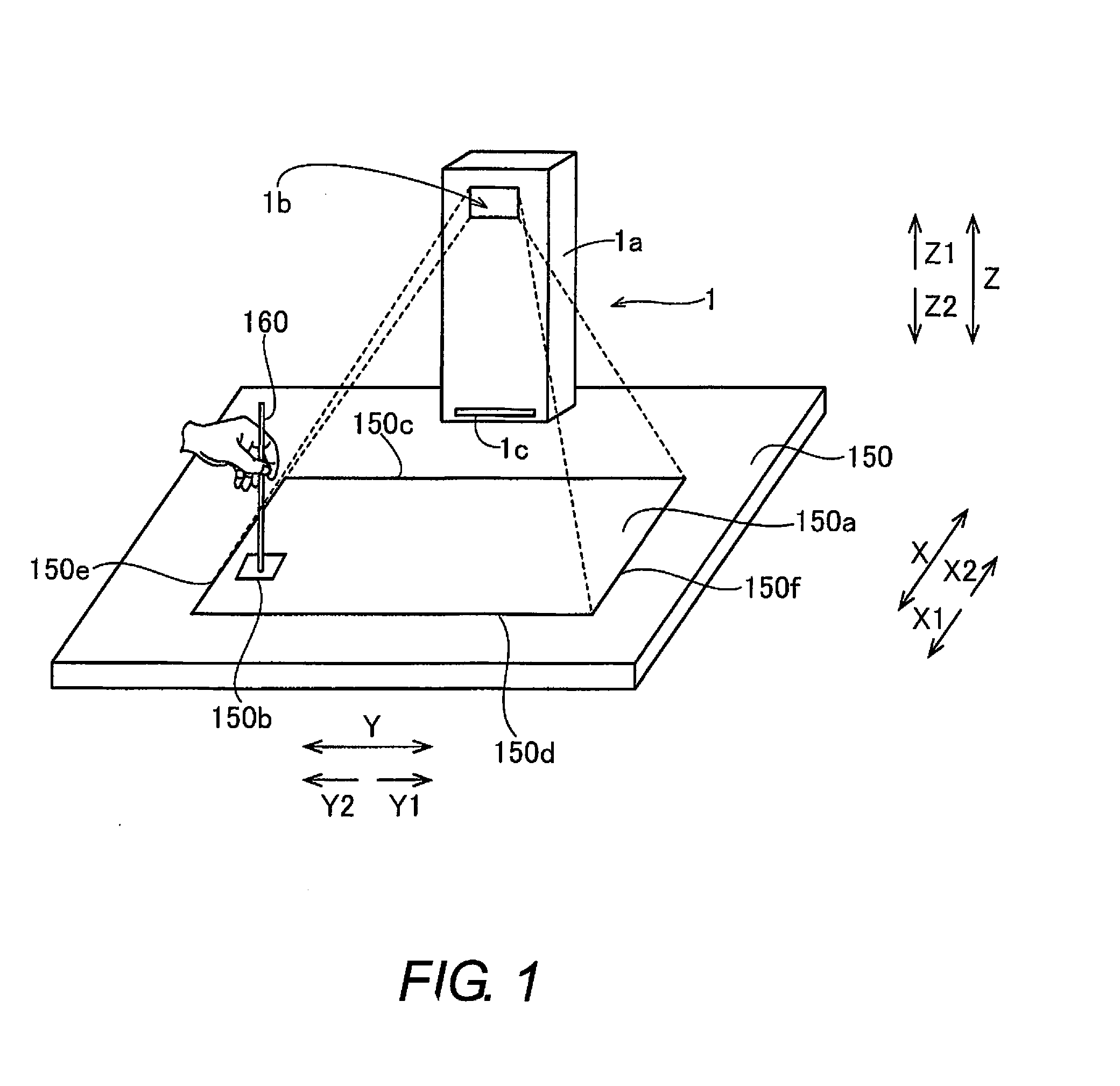
[0028]As shown in FIG. 1, the projector 1 in accordance with the first embodiment is used when placed on a table 150 or the like. The projector 1 includes on its upper side (Z1 direction side) an opening 1b through which laser light is emitted from a housing 1a toward a projection surface 150a. Also, the projector 1 includes on the projection surface 150a side (Z2 direction side) an opening 1c through which the laser light reflected by a detection object 160 is incident on the inside of the housing 1a. The opening 1c is provided on a side face of the housing 1a on the projection surface 150a side (X1 direction side). This projector 1 is configured so that an image 150b (video) of an icon (button) or the like to be selected by the user is projected onto the projection surface 150a on the table 150. The projector 1 is also configured so that a touch operation, in which the image 150b pr...
second embodiment
[0059]Referring now to FIGS. 7 and 8, a projector 2 in accordance with a second embodiment will now be explained. In view of the similarity between the first and second embodiments, the parts of the second embodiment that are identical to the parts of the first embodiment will be given the same reference numerals as the parts of the first embodiment. Moreover, the descriptions of the parts of the second embodiment that are identical to the parts of the first embodiment may be omitted for the sake of brevity.
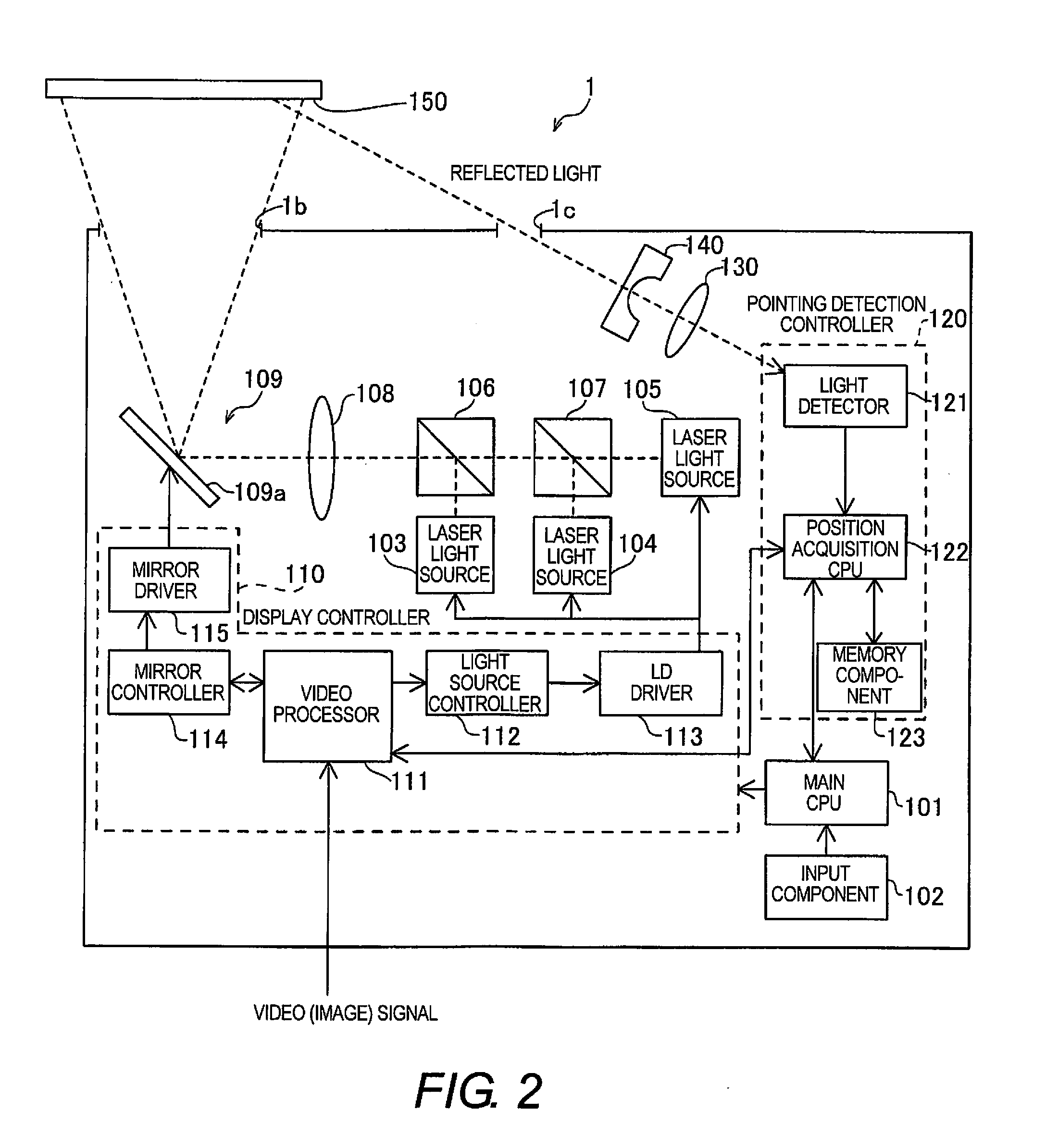
[0060]In the first embodiment, the prism 140 is disposed on the projection surface 150a side of the converging lens 130. In the second embodiment, with the projector 2, a light guide member 240 is disposed to the side of the region between the converging lens 130 and the light detector 121 along the optical axis 132 of the converging lens 130. In the following description, members that are numbered the same as in the first embodiment above and shown in FIG. 2 are the same as in t...
third embodiment
[0068]Referring now to FIGS. 9 and 10, a projector 3 in accordance with a third embodiment will now be explained. In view of the similarity between the first and third embodiments, the parts of the third embodiment that are identical to the parts of the first embodiment will be given the same reference numerals as the parts of the first embodiment. Moreover, the descriptions of the parts of the third embodiment that are identical to the parts of the first embodiment may be omitted for the sake of brevity.
[0069]In the first embodiment, the prism 140 is disposed on the projection surface 150a side of the converging lens 130. In the third embodiment, with the projector 3, a low reflection-processed prism 340 that has undergone low reflection-processing is disposed between the converging lens 130 and the light detector 121 along the optical axis 132 of the converging lens 130. The low reflection-processed prism 340 is an example of the “light guide member” of the present invention. In t...
PUM
 Abstract
Description
Claims
Application Information