Fuel injection control device

a control device and fuel injection technology, applied in the direction of electric control, machines/engines, mechanical equipment, etc., can solve the problems of undesirable deterioration of detection accuracy and increase in the implementation scale of control devices, and achieve the suppression of erroneous detection of timing detection modes, wide detection range, and reduced differences

Active Publication Date: 2019-06-13
TOYOTA JIDOSHA KK
View PDF6 Cites 1 Cited by
  • Summary
  • Abstract
  • Description
  • Claims
  • Application Information

AI Technical Summary

Benefits of technology

[0014]According to the present disclosure, the valve closing detection unit can execute either of the induced electromotive force quantity detection mode and the timing detection mode. Consequently, the valve closing detection unit can be downsized further than a configuration of executing both of the modes simultaneously. Further, the selection unit selects the timing detection mode when the requested injection quantity is larger than the reference injection quantity and selects the electromotive force quantity detection mode when the requested injection quantity is smaller than the reference injection quantity. The timing detection mode is superior to the electromotive force quantity detection mode in detection accuracy but has a detection range smaller than the electromotive force quantity detection mode. In the case of the reference injection quantity or more that is in the detection range of being detectable by the timing detection mode therefore, it is possible to select the timing detection mode and use the timing detection mode suitably. Further, in the case of less than the reference injection quantity that is in the detection range of not being detectable by the timing detection mode, the electromotive force quantity detection mode is selected. Consequently, the electromotive force quantity detection mode can make up for the narrow detection range of the timing detection mode. As a result, a fuel injection device that can secure both of the detection accuracy and the detection range of a valve closing timing can be materialized.
[0015]Further, in the present disclosure, a correction coefficient is calculated so as to reduce the difference between an estimated injection quantity estimated by using a valve closing timing detected by an electromotive force quantity detection mode and a requested injection quantity. Then a selection unit uses a value corrected by the correction coefficient for a requested injection quantity of determining whether or not a timing detection mode is selected. Then the selection unit selects not the timing detection mode but the electromotive force quantity detection mode when the calculation of the correction coefficient is yet to be completed. Since the detection range of the timing detection mode is narrow as stated earlier, when the difference between a requested injection quantity and an actual injection quantity is large while the timing detection mode is used, the actual injection quantity may not be in the detection range of the timing detection mode undesirably. Consequently, in order to reduce the difference between a requested injection quantity and an actual injection quantity, firstly the requested injection quantity is corrected by using an estimated injection quantity estimated by using a valve closing timing of the electromotive force quantity detection mode having a wide detection range. As a result, the difference between the requested injection quantity and an actual injection quantity can be reduced and thus the actual injection quantity can be in the detection range of the timing detection mode. It is therefore possible to switch the electromotive force quantity detection mode and the timing detection mode under appropriate conditions and make use of the mutual advantages of both the detection modes while erroneous detection by the timing detection mode is suppressed.

Problems solved by technology

In the induced electromotive force quantity detection, an electromotive force quantity tends to be influenced by external disturbance and hence the detection accuracy may deteriorate undesirably.
In order to execute both of the detection modes however, processing capabilities have to be increased and the implementation scale of a control device may increase undesirably.

Method used


Image

  • Fuel injection control device
  • Fuel injection control device
  • Fuel injection control device

Examples


first embodiment

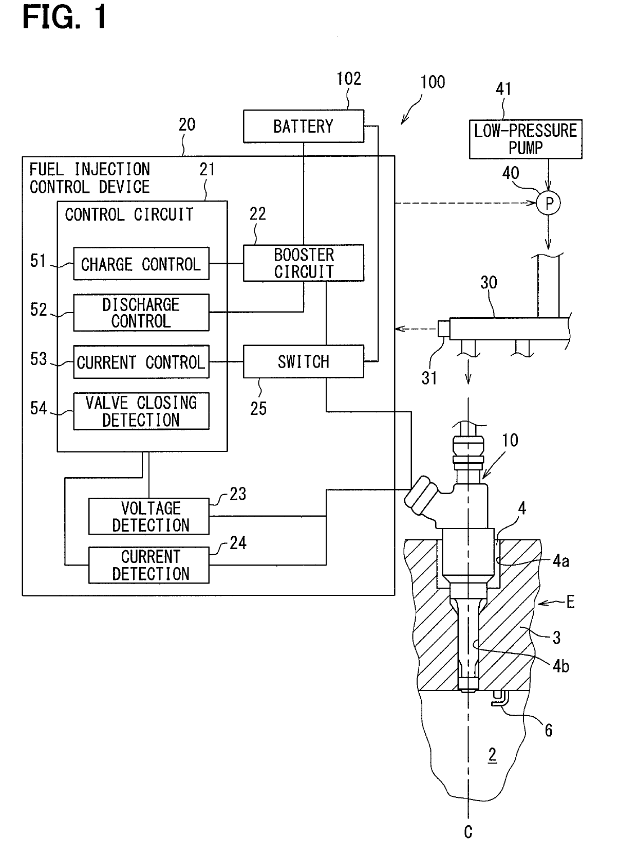
[0025]A first embodiment according to the present disclosure is explained in reference to FIGS. 1 to 8. A fuel injection system 100 shown in FIG. 1 includes a plurality of fuel injection valves 10 and a fuel injection control device 20. The fuel injection control device 20 controls the opening and closing of the fuel injection valves 10 and controls fuel injection into a combustion chamber 2 of an internal combustion engine E. The fuel injection valves 10: are installed in an internal combustion engine E of an ignition type, for example a gasoline engine; and inject a fuel directly into a plurality of combustion chambers 2 of the internal combustion engine E respectively. A mounting hole 4 penetrating concentrically with an axis C of a cylinder is formed in a cylinder head 3 constituting the combustion chamber 2. A fuel injection valve 10 is inserted into and fixed to the mounting hole 4 so that the tip may be exposed into the combustion chamber 2.

[0026]A fuel supplied to the fuel i...


PUM


Abstract

A fuel injection control device includes a valve closing detection unit (54) to detect a valve closing timing by using either of an electromotive force quantity detection mode and a timing detection mode, a selection unit (21) to select either of the electromotive force quantity detection mode and the timing detection mode for detecting the valve closing timing, and a correction unit (21) to calculate a correction coefficient for correcting a requested injection quantity so as to reduce the difference between an estimated injection quantity and the requested injection quantity, and the selection unit selects the electromotive force quantity detection mode regardless of the value of the requested injection quantity when the calculation of the correction coefficient is not completed.

Description

CROSS REFERENCE TO RELATED APPLICATION[0001]This application is based on Japanese Patent Application No. 2016-93316 filed on May 6, 2016, the disclosure of which is incorporated herein by reference.TECHNICAL FIELD[0002]The present disclosure relates to a fuel injection control device having a fuel injection valve of an electromagnetically driven type.BACKGROUND ART[0003]A fuel injection control device controls injection through a fuel injection valve of an electromagnetically driven type incorporated in an internal combustion engine. Specifically, a fuel injection control device calculates a requested injection quantity in response to the operational status of an internal combustion engine and conducts a coil by an injection command pulse of a pulse width corresponding to the requested injection quantity. As a result, a magnetic attraction force is generated in the coil, a valve body of a fuel injection valve is driven to valve opening, and a fuel is controlled so as to be injected ...

Claims


Application Information

Patent Timeline
Patent Type & Authority Applications(United States)
IPC IPC(8): F02D41/20F02D41/24F02D41/40F02M51/06
CPCF02D41/20F02D41/247F02D41/401F02M51/0685F02D2041/2051F02D2041/2055F02D2041/2058F02D2200/0614F02D2200/063Y02T10/40
Inventor SATAKE, NOBUYUKIMURASE, EIJINAKANO, TOMOHIRO
Owner TOYOTA JIDOSHA KK
Why Eureka
Try Eureka