Eureka AIR delivers breakthrough ideas for toughest innovation challenges, trusted by R&D personnel around the world.

Electrical connector with spring clip

Active Publication Date: 2015-01-29
BRIDGEPORT FITTINGS LLC +1
View PDF4 Cites 1 Cited by
  • Summary
  • Abstract
  • Description
  • Claims
  • Application Information

AI Technical Summary

Benefits of technology

The present invention provides an electrical connector with an integral spring clip that allows for easy and secure connection to an outlet box. The connector assembly does not require a typical annular stop flange to limit insertion and achieve electrical continuity. Instead, curved springs are used to improve electrical continuity and secure the connector assembly at the knock-out hole, preventing rotation. The technical effect of this invention is to simplify the installation process and improve the reliability of the electrical connection.

Problems solved by technology

As the snap-type connectors are constructed of several pieces, the complexity of the connector is increased.

Method used


Image

  • Electrical connector with spring clip
  • Electrical connector with spring clip
  • Electrical connector with spring clip

Examples


Embodiment Construction

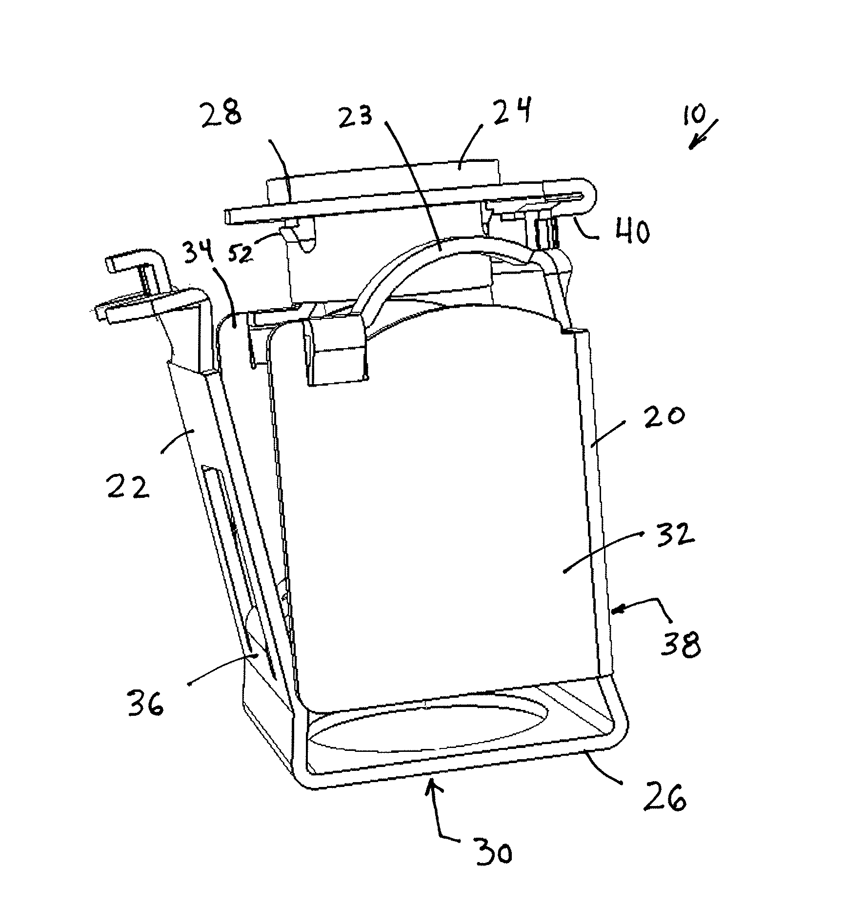
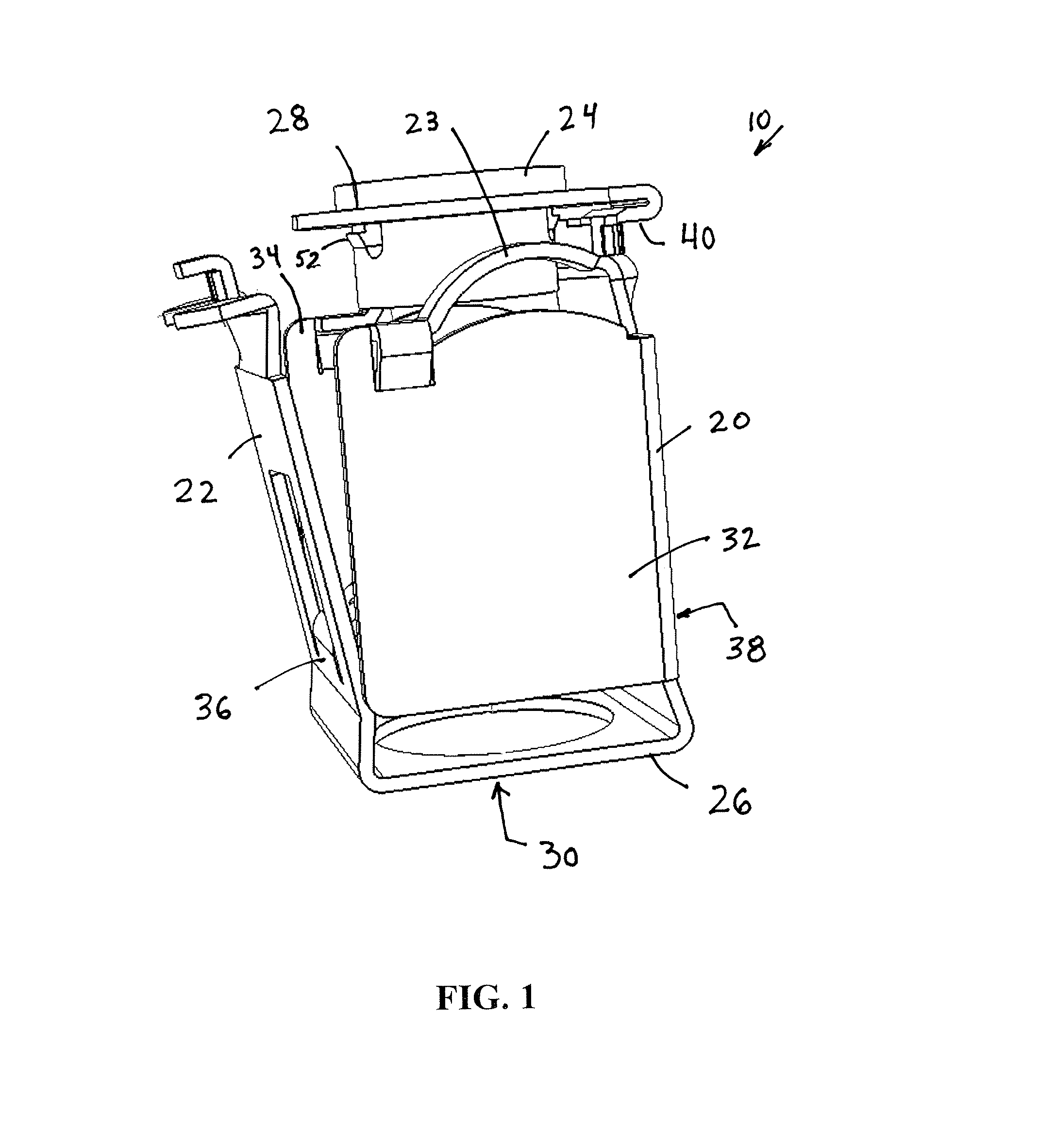
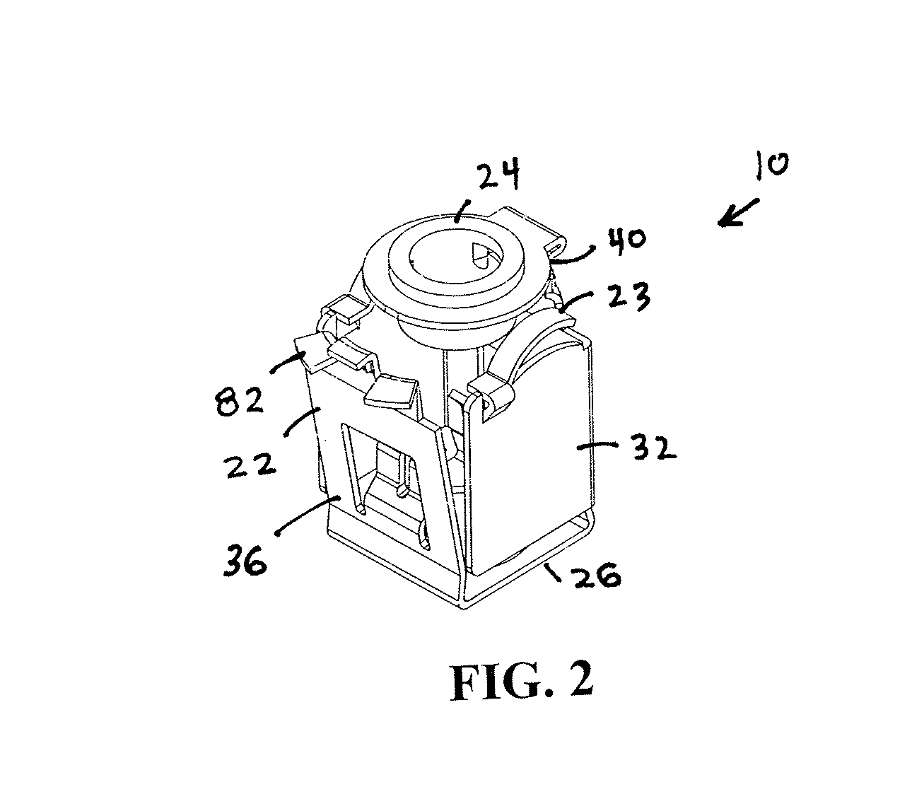
[0030]Referring to the drawings, FIGS. 1 and 2 are perspective views of the first embodiment of an electrical connector assembly 10 in accordance with the present invention. FIGS. 3-5 depict connector assembly 10 between electrical box 12 and electrical cable 14. As described hereinafter, connector assembly 10 is used to couple electrical cable 14 at knock-out hole 16 of electrical box 12. FIGS. 6-10 are additional views of connector assembly 10. FIGS. 11-13 depict connector assembly 10 connected to electrical cable 14. FIGS. 14-16 are cross-sectional views of connector assembly 10. FIG. 17 is a plan view of a metal blank used to form connector body 20.

[0031]Referring to FIGS. 1 and 2, connector assembly 10 includes connector body 20 defining a spring clip 22 and curved springs 23, and insulator 24. Connector body 20 is formed with an inlet end portion 26 and an outlet end portion 28 and a bore 30 extending therethrough. Connector body 20 includes a pair of generally parallel sides ...


PUM


Abstract

A connector assembly including a connector body with a spring clip including a first free end for engaging a side wall of an electrical box upon installation. During insertion of the connector body the first free end is deformed so as to permit further insertion. Once the connector body is fully inserted, the spring clip cooperates with a lug on the connector body to hold the connector assembly onto the electrical box.

Description

TECHNICAL FIELD[0001]The invention is directed to a further advancement in the field of electrical connector assemblies. More specifically, this application relates to an electrical connector assembly having an integral retaining spring for facilitating the connection of the connector assembly and associated cable, wire conductor and the like to an electrical box.BACKGROUND OF THE INVENTION[0002]Electrical connectors are commonly used for attaching electrical conductors, cables, wires, electrical metal tubing (EMT) or the like to an electric box, e.g. a junction box, outlet box, switch box, fuse box, or other similar type of electric box. Such known electrical connectors are either of a type that are secured to an electric box by a threaded lock nut or by means of a circular snap fit retaining ring of the type disclosed in U.S. Pat. Nos. 6,860,758; 6,444,907; 5,189,258; 5,266,050; and 5,171,164, for example.[0003]So called “snap fit” connectors have been in use for some time, includ...

Claims


Application Information

Patent Timeline
IPC IPC(8): H01R13/627
CPCH01R13/627H01R13/743H01R24/564
Inventor SMITH, LAWRENCE J.
Owner BRIDGEPORT FITTINGS LLC
Why Eureka
Eureka Blog
Learn More