Cable support

a cable support and cable technology, applied in the direction of electrical/fluid circuits, vehicle components, electrical apparatus, etc., can solve the problems of bar and locking member rotation, loosening of the locking member, and difficulty in molding

Active Publication Date: 2018-02-22
HELLERMANN TYTON LTD
View PDF8 Cites 7 Cited by
  • Summary
  • Abstract
  • Description
  • Claims
  • Application Information

AI Technical Summary

Benefits of technology

[0010]The cable support has a support surface to which the cable or cables are secured, and the cable support surface preferably has a concave profile in a direction transverse to the length of the blade. The concave profile corresponds to the curved surface of the cables, and increases the surface contact between the blade and the cables.
[0015]The locking member is preferably mounted within the bore of the mounting member. The locking member may inserted into the mounting member in the insertion direction with the mounting member including one or more stop members to limit axial insertion of the locking member located at the inner end of the bore. One or more retaining members are also provided to prevent removal of the locking member in the opposite direction once inserted, with the locking member being retained between the retaining member and the stop member or members.

Problems solved by technology

Small eyelets and holes required for fasteners such as cable ties present difficulties in molding.
More problematically, any rotational forces applied to the support bar cause the bar and the locking member to rotate relative to the mounting stud.
During rotation the locking member rotationally scores the mounting stud, leading to loosening of the locking member and potential failure of the mounting stud.

Method used


Image

  • Cable support
  • Cable support
  • Cable support

Examples


first embodiment

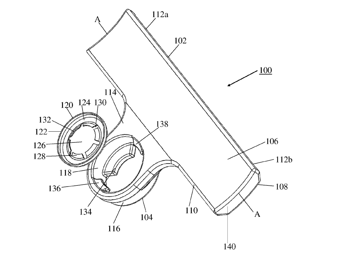
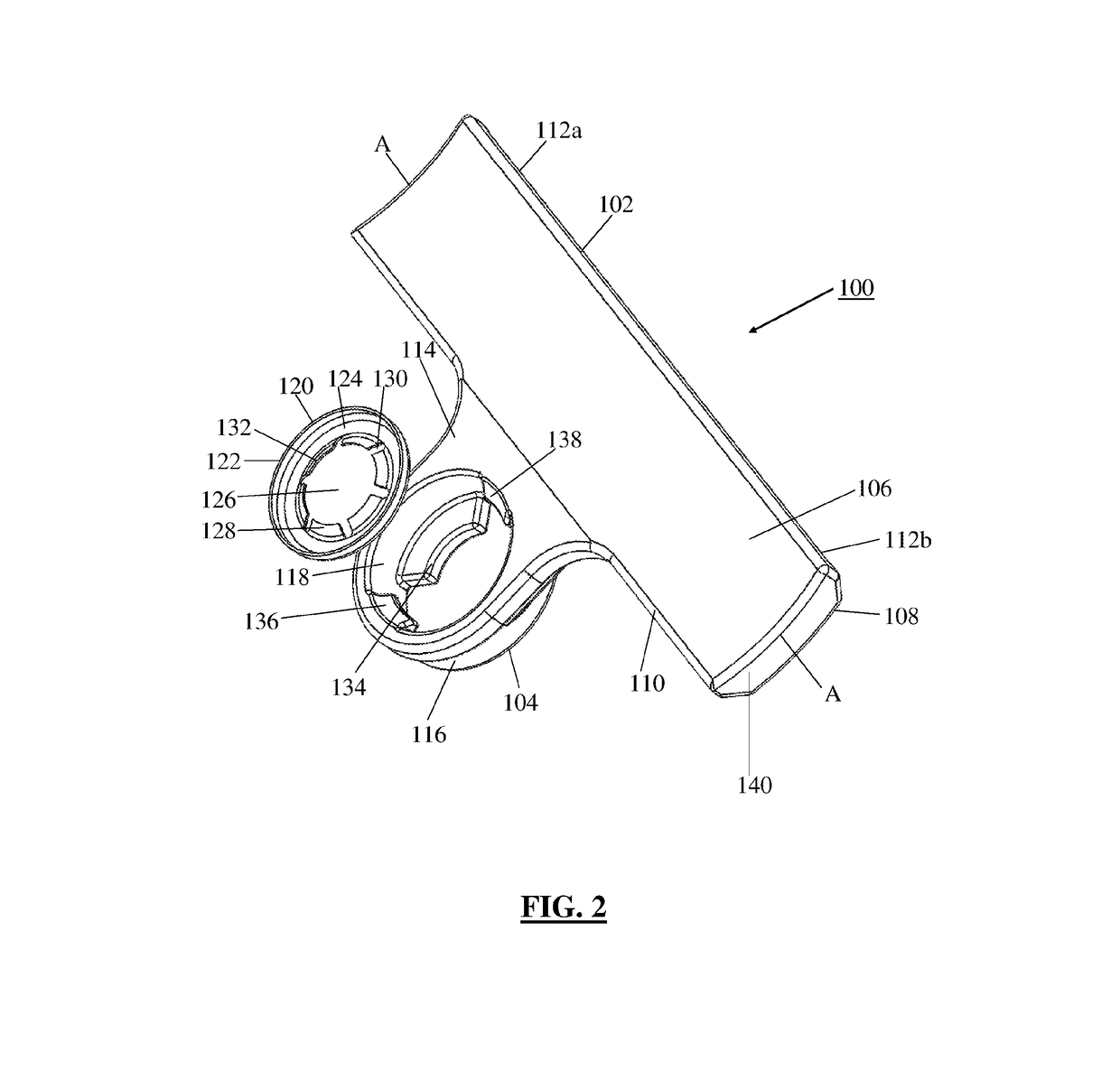
[0061]an electrical cable support 100 is illustrated in FIG. 2. The electrical cable support 100 includes an elongate rectangular bar section defining a support member 102, and a mounting member 104, for mounting the wiring support to a corresponding plastic mounting stud. The mounting stud may be integrally molded with, or separately mounted to, a support substrate. The support member 102 has an elongate rectangular form with a longitudinal axis A-A. The support member 102 includes a mounting surface 106 which, when in use, faces away from the trim panel and away from the insertion direction, and a corresponding inner surface 108. When in use, the wiring is secured to the mounting surface 106. The mounting surface 106 has a concave scalloped profile in the direction transverse to the longitudinal axis that is configured to accommodate the curved profile of a wiring bundle. The mounting member 104 extends from the lower edge 110 of the support member 102 and is centrally located alo...

second embodiment

[0070]a cable support 201 is shown in FIG. 4 in which the cable support 201 includes a pair of wings or tabs 240 extending laterally from either side of the cylindrical body 216 of the clip section 204 in a radial direction. The tabs 240 taper inwardly towards a curved outer edge 242. The tabs 240 each include an outer engagement surface 244 facing away from the insertion direction. The engagement surface 244 of the tabs 240 increase the surface area available to which the user may apply pressure in the insertion direction to force the cable support 201 over the mounting stud 252. The increased surface area increases the distribution of force across the user's fingers thereby increasing comfort. In addition, the tabs 240 allow pressure to be applied at an increased radial distance, thereby mitigating the risk of the stub striking the user's fingers and causing injury as the cable support 201 is forced into the mounting stud 252.

[0071]As shown in FIG. 5, the reverse side of the tabs ...

third embodiment

[0073]a cable support 301 is shown in FIG. 7. In this embodiment, the height of the main body 316 of the clip section 304 is extended to provide protection for the user's thumbs. As in the previous embodiments, the clip section 304 is pressed over the mounting stud 252 and the mounting stud 252 projects out through the upper end of the clip section. In use, the projecting stud 252 may contact the user's thumbs as the clip is pressed into place, causing inconvenience and potentially injuring the user. The main body 316 is therefore provided with a collar section 360 that extends upwardly above the height of the blade 302. The collar section 360 is cylindrical with the bore 318 extending therethrough. The upper surface 362 of the collar defines the upper edge of the main body 316, and the main body 316 also has a lower edge. The press tabs 340 project laterally from the upper surface 362 of the collar section 360 and are spaced vertically above the upper surface of the blade 302. The ...


PUM


Abstract

A cable support is provided that includes an elongate support member for supporting a cable or cables secured thereto. A mounting member is connected to the support member and secures the support member to amounting stud on a trim panel or other support substrate. The mounting member comprises a bore for receiving the mounting stud. A locking member is provided that has an aperture formed therein for receiving the mounting stud. The locking member is connected to the mounting member in axial alignment with the bore and rotatably connected to the mounting member such that the mounting member and support member are rotatable relative to the locking member.

Description

CROSS REFERENCE TO A APPLICATIONS[0001]This application is a bypass continuation-in-part application and claims benefit under 35 U.S.C. §365(c) of International Patent Application PCT / GB2016 / 051220 filed Apr. 28, 2016 which claims the benefit of Great Britain Patent Application Serial No. 1507400.8, filed Apr. 30, 2015, the entire disclosure of each of which are hereby incorporated by reference.TECHNICAL FIELD OF INVENTION[0002]The present invention relates to a cable support, and in particular to a bracket for securing electrical cables within a vehicle.BACKGROUND OF THE INVENTION[0003]Body panels such as doors for passenger vehicles typically comprise a main body forming the structure of the door or other panel, and an interior trim panel assembly. The trim panel assembly provides an aesthetically pleasing appearance to the interior surface of the door that also enables the mechanical and electrical elements of the door to be concealed from view. It is known to use trim panels for...

Claims


Application Information

Patent Timeline
Patent Type & Authority Applications(United States)
IPC IPC(8): B60R16/02H02G3/32F16L3/18
CPCB60R16/0215H02G3/32F16L3/18F16L3/16H02G3/30
Inventor CHAPMAN, PHILIP
Owner HELLERMANN TYTON LTD
Why Eureka
Try Eureka