Pressing Force Sensor

a technology of pressure sensor and pressure, applied in piezoelectric/electrostrictive/magnetostrictive devices, piezoelectric/electrostrictive/magnetostriction machines, etc., can solve the problems of inability to obtain predetermined detection sensitivity or fragile piezoelectric crystalline thin film external force, so as to reduce detection sensitivity and detect operator operation more reliably

Active Publication Date: 2015-02-05
MURATA MFG CO LTD
View PDF2 Cites 17 Cited by
  • Summary
  • Abstract
  • Description
  • Claims
  • Application Information

AI Technical Summary

Benefits of technology

[0029]With this structure, the space portion of the piezoelectric sheet is not reliably pushed in by an operating method of an operator but the push-in member. Consequently, it is possible to detect the operation of the o

Problems solved by technology

For this reason, the piezoelectric crystalline thin film is fragile to external force or predeterm

Method used


Image

  • Pressing Force Sensor
  • Pressing Force Sensor
  • Pressing Force Sensor

Examples


first embodiment

[0078]A pressing force sensor 10A according to the present embodiment includes plural sets of an opening portion and first and second electrodes described in the

[0079]A flat membrane type piezoelectric element 20A includes a piezoelectric sheet 210A. The piezoelectric sheet 210A is formed by the same material as the piezoelectric sheet 210 and is stretched in a uniaxial direction. In the present embodiment, the piezoelectric sheet 210A is stretched in the uniaxial direction to form an angle of 45° with respect to long and short directions in the same manner as the piezoelectric sheet 210 according to the first embodiment.

[0080]A plurality of first electrodes 221, 222, 223, 224, 225 and 226 (hereinafter referred collectively to as 221 to 226) is formed on a first main surface of the piezoelectric sheet 210A. The plurality of first electrodes 221 to 226 take rectangular shapes. The plurality of first electrodes 221 to 226 are arranged with respective long directions made coincident wi...

third embodiment

[0102]A pressing force sensor 10C according to the present embodiment is obtained by further adding a push-in member 50 to the pressing force sensor 10B according to the

[0103]A flat membrane type piezoelectric element 20C is the same as the flat membrane type piezoelectric element 20B according to the third embodiment, a support 30C is the same as the support 30B according to the third embodiment, and a protective layer 40C is the same as the protective layer 40B according to the third embodiment. The protective layer 40C can be omitted.

[0104]A surface of the support 30C at an opposite side to the flat membrane type piezoelectric element 20C abuts on a base circuit board 820 of an operating device in which the pressing force sensor 10C is to be incorporated.

[0105]The push-in member 50 is provided on an opposite side of the flat membrane type piezoelectric element 20C at the protective layer 40C. The push-in member 50 includes a flat plate portion 510, a neck portion 520 and a head p...


PUM


Abstract

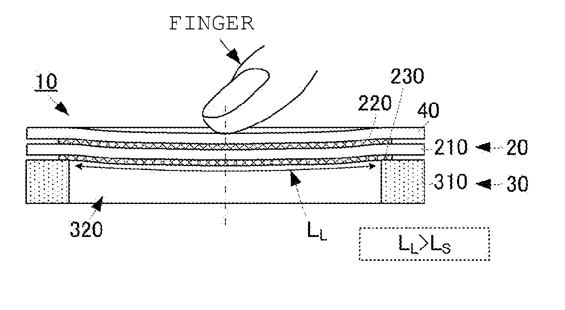
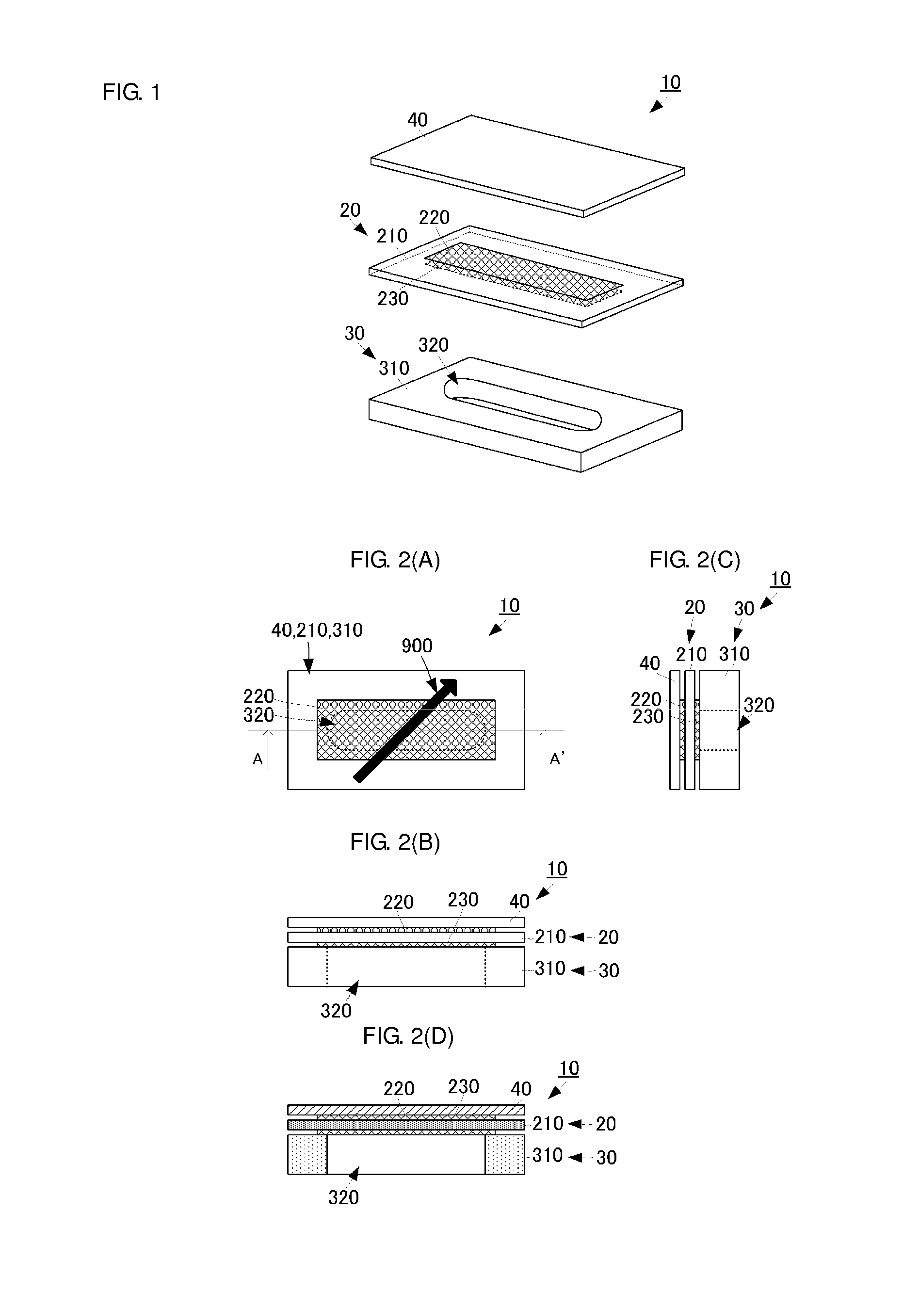
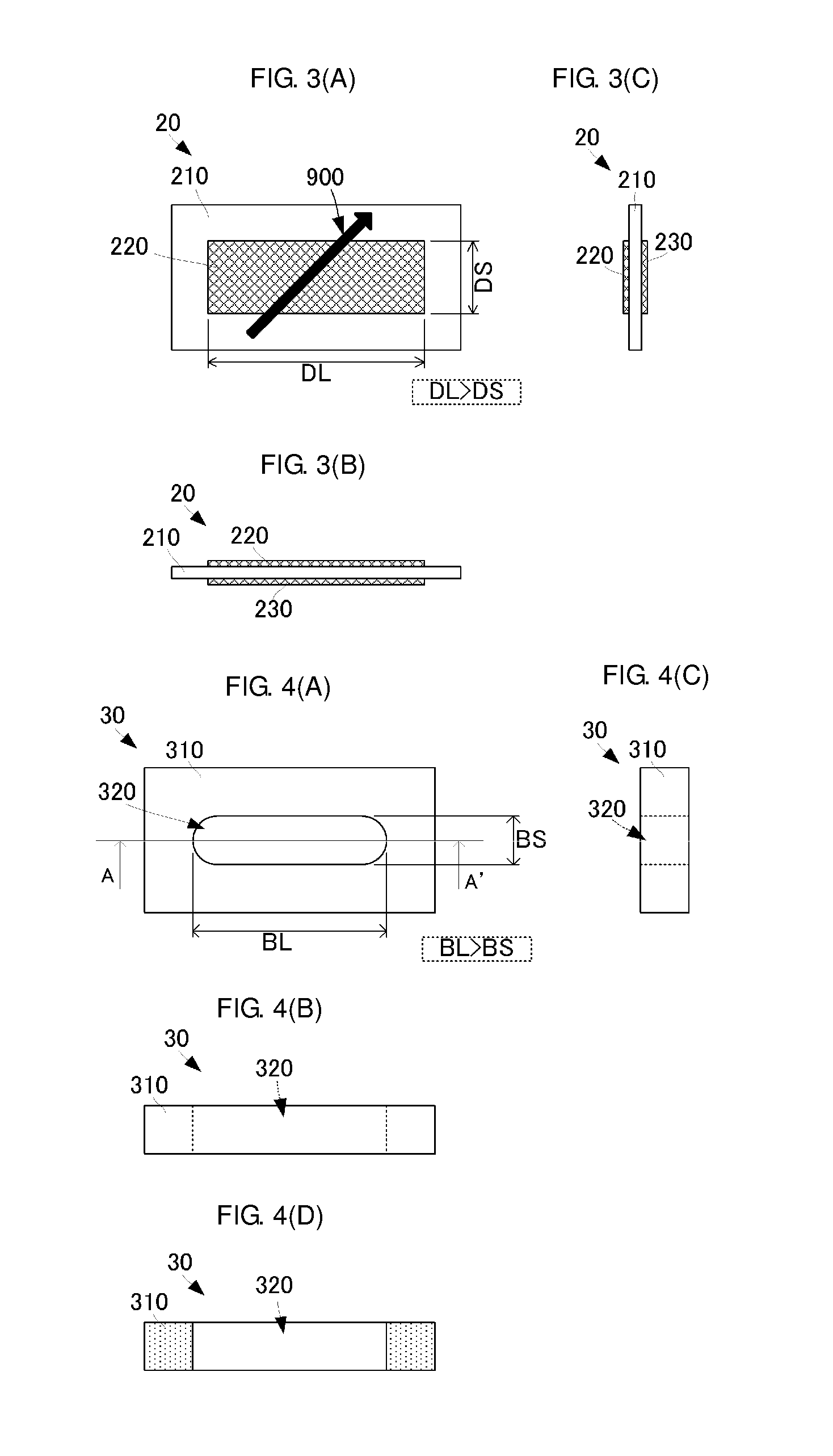
A pressing force sensor that includes a flat membrane piezoelectric element and a support. The flat membrane piezoelectric element includes a piezoelectric sheet having a piezoelectric constant d14. A first electrode is formed on a first main surface of the piezoelectric sheet and a second electrode is formed on a second main surface thereof. Long directions of the first electrode and the second electrode and a uniaxial stretching direction of the piezoelectric sheet form an angle of 45°. An opening portion having an elliptical section is formed on the support. The flat membrane piezoelectric element abuts the opening portion of the support. The support and the flat membrane piezoelectric element are disposed such that the opening portion is included within an area of the second electrode.

Description

CROSS REFERENCE TO RELATED APPLICATIONS[0001]The present application is a continuation of International application No. PCT / JP2013 / 061146, filed Apr. 15, 2013, which claims priority to Japanese Patent Application No. 2012-093525, filed Apr. 17, 2012, the entire contents of each of which are incorporated herein by reference.FIELD OF THE INVENTION[0002]The present invention relates to a pressing force sensor for detecting pressing force from an outside by using a flat membrane-shaped piezoelectric element.BACKGROUND OF THE INVENTION[0003]Conventionally, there are various pressing force sensors using a flat membrane-shaped piezoelectric element. Patent Document 1 describes a pressing force sensor having a flat membrane-shaped piezoelectric element formed on a main surface of a flexible substrate. Referring to the pressing force sensor described in the Patent Document 1, a piezoelectric crystalline thin film is formed on a whole surface of a flexible substrate having a square main surfa...

Claims


Application Information

Patent Timeline
IPC IPC(8): G01L1/16H01L41/053H01L41/113
CPCG01L1/16H01L41/1132H01L41/053Y10S977/742B82Y15/00Y10S977/762Y10S977/956H10N30/883H10N30/308H10N30/302H10N30/857H10N30/88
Inventor KAWAMURA, HIDEKIANDO, MASAMICHI
Owner MURATA MFG CO LTD
Why Eureka
Try Eureka