Method for determining the tread depth of a vehicle pneumatic tire

a technology of pneumatic tires and profile depths, which is applied in the direction of instruments, television systems, and vehicle owners can only approximate the current profile depth, and the risk of cracks being produced in the circumferential grooves,

Active Publication Date: 2015-02-05
CONTINENTAL REIFEN DEUTSCHLAND GMBH
View PDF4 Cites 21 Cited by
  • Summary
  • Abstract
  • Description
  • Claims
  • Application Information

AI Technical Summary

Benefits of technology

[0013]The positioning mask can furthermore display at least one measurement marking which is positioned at an incision end of the photographed incision. This positioning can be performed automatically or manually by the measurement marking being moved over the

Problems solved by technology

However, the vehicle owner or vehicle user can only roughly estimate the current profile depth.
Furthermore, there is a risk of cracks being produced in the circumferential grooves in the case of wear indicators of th

Method used


Image

  • Method for determining the tread depth of a vehicle pneumatic tire
  • Method for determining the tread depth of a vehicle pneumatic tire
  • Method for determining the tread depth of a vehicle pneumatic tire

Examples


Embodiment Construction

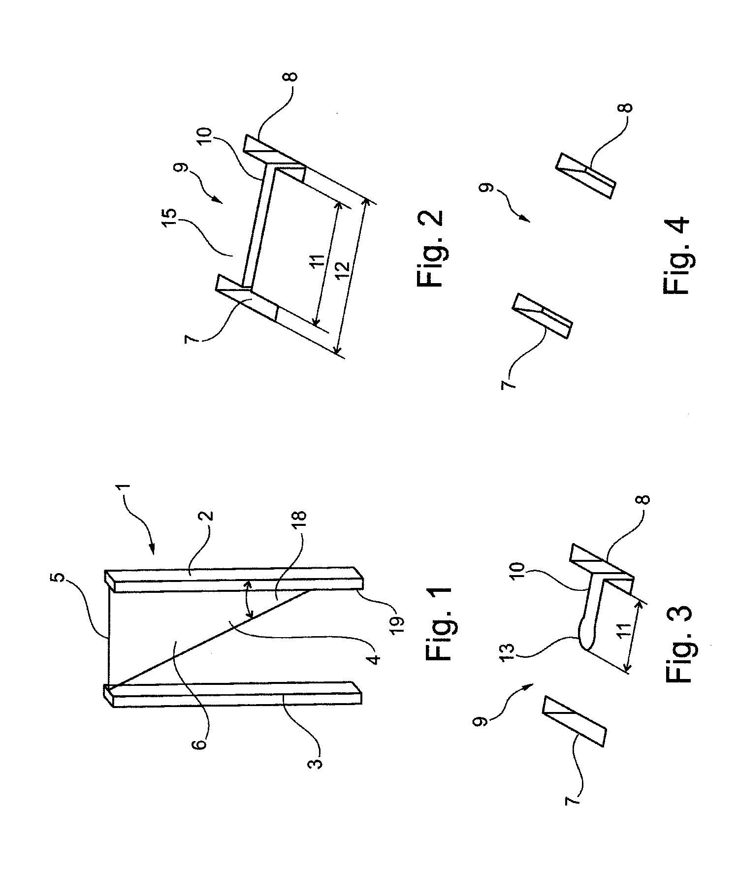
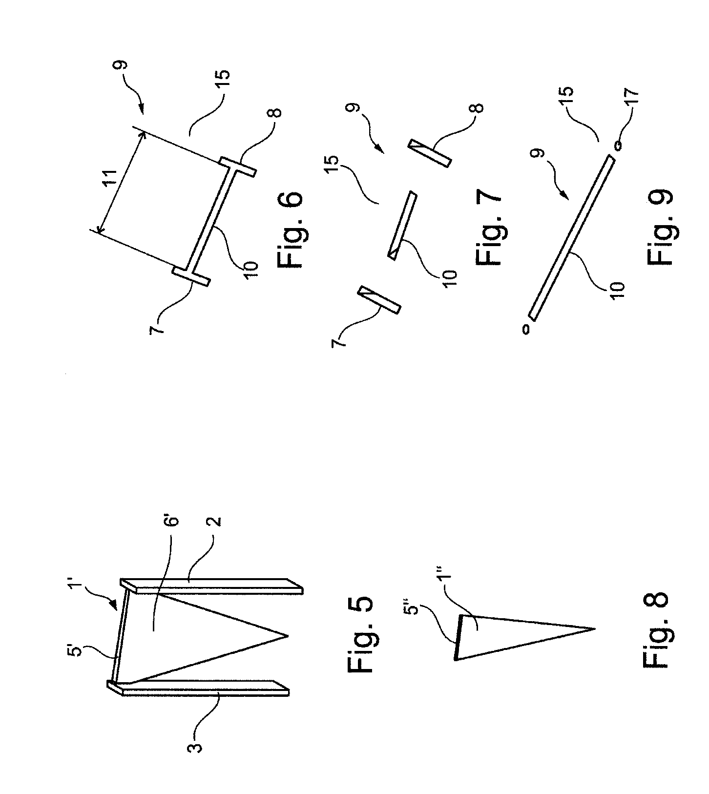
[0025]FIG. 1 shows a sipe 1 for forming a wear indicator. On its upper sipe side 5, the sipe 1 is incorporated, in a manner which is not shown, into a vulcanization mold which impresses the profile into the unvulcanized tread of the pneumatic vehicle tire. The sipe 1 has a triangular sipe part 6 which forms a straight incision in the tread of the tire, which incision serves as a wear indicator. Further sipe parts 2 and 3, which enter the tread in the radial direction, have the function of forming boundary incisions (7, 8) in the tread as shown in FIGS. 2 and 3. One side of the triangular sipe part 6 forms the sipe side 5, a further side runs along the sipe part 2, and the third side 4, which forms the hypotenuse of the triangle, connects the upper end of the sipe part 3 to the lower region of the sipe part 2. This connecting sipe side 4 can be provided with a rounded portion which assists the molding process after the vulcanization of the tire. The boundary incisions 7 and 8 prefera...


PUM


Abstract

A method for determining the profile depth of a tread of a pneumatic vehicle tire wherein the tread has a wear indicator. The wear indicator has an incision extending in the radial direction of the tire. The incision has a length visible on the tread and the length becomes shorter as wear increases. The wear indicator has two reference marks at a distance from each other. The distance is configured to remain constant and visible throughout the tread wear. A photo of the incision and the reference marks is generated via an application program of a mobile phone having a camera and an image screen. A current profile depth is calculated from the distance of the reference marks and the length of the incision via the application program. The current profile depth and/or a remaining profile depth are displayed until a minimal profile depth is reached on the screen.

Description

CROSS REFERENCE TO RELATED APPLICATIONS[0001]This application is a continuation application of international patent application PCT / EP2013 / 055115, filed Mar. 13, 2013, designating the United States and claiming priority from German application 10 2012 103 420.6, filed Apr. 19, 2012, and the entire content of both applications is incorporated herein by reference.FIELD OF THE INVENTION[0002]The invention relates to a method for determining the profile depth of the tread of a pneumatic vehicle tire, wherein at least one wear indicator is provided in the tread. The wear indicator has at least one incision which runs in the radial direction. The length of the incision, which is visible on the outside of the tread, becomes shorter in a defined manner as wear increases. The wear indicator has at least two reference marks, the mutual distance between the two reference marks remaining constant and visible over the tread wear. The invention further relates to a mobile telephone, in particular...

Claims


Application Information

Patent Timeline
IPC IPC(8): B60C11/24G06T7/00H04N5/232
CPCB60C11/24H04N5/23293G06T2207/30252G06T2207/10004G06T7/0008G01B11/22B60C11/246H04N23/635
Inventor BOGENSCHUETZ, PETER
Owner CONTINENTAL REIFEN DEUTSCHLAND GMBH
Why Eureka
Try Eureka