Method and system for encoding a 3D video signal, encoder for encoding a 3-D video signal, encoded 3D video signal, method and system for decoding a 3D video signal, decoder for decoding a 3D video signal.

a technology of video signal and encoder, applied in the field of video encoding and decoding, can solve the problems of insufficient processing power and/or transmission capacity, glass wear to produce any effect, and insufficient amount of processing and/or transmission of digital image signals, etc., to reduce the amount of overall data, reduce the amount of additional layers, and reduce the effect of effective data

Inactive Publication Date: 2011-06-23
KONINKLIJKE PHILIPS ELECTRONICS NV
View PDF4 Cites 18 Cited by
  • Summary
  • Abstract
  • Description
  • Claims
  • Application Information

AI Technical Summary

Benefits of technology

[0040]In all cases, the additional streams will be relatively small due to the fact that a single data-element describes all the 16×16 pixels in a macroblock or even more pixels in a segment exclusively and at the same time. The sum of effective data has increased a little, however the amount of further layers is significantly reduced, which reduces the overall data amount.
[0041]The common layer(s), plus the additional stream or additional streams, can then travel for instance over a bandwidth lim

Problems solved by technology

A disadvantage of such a system is that glasses have to be worn to produce any effect.
This is unpleasant for those observers who are not familiar with wearing glasses and a potential problem for those already wearing glasses, since the additional pair of glasses does not always fit.
Because of the massive amounts of data inherent in digital imaging, the processing and/or the transmission of digital image signals form significant problems.
In many circumstances the available processing power and/or transmission capacity is insufficient to process and/or transmit high quality video signals.
The amounts of raw digital information are u

Method used


Image

  • Method and system for encoding a 3D video signal, encoder for encoding a 3-D video signal, encoded 3D video signal, method and system for decoding a 3D video signal, decoder for decoding a 3D video signal.
  • Method and system for encoding a 3D video signal, encoder for encoding a 3-D video signal, encoded 3D video signal, method and system for decoding a 3D video signal, decoder for decoding a 3D video signal.
  • Method and system for encoding a 3D video signal, encoder for encoding a 3-D video signal, encoded 3D video signal, method and system for decoding a 3D video signal, decoder for decoding a 3D video signal.

Examples


Embodiment Construction

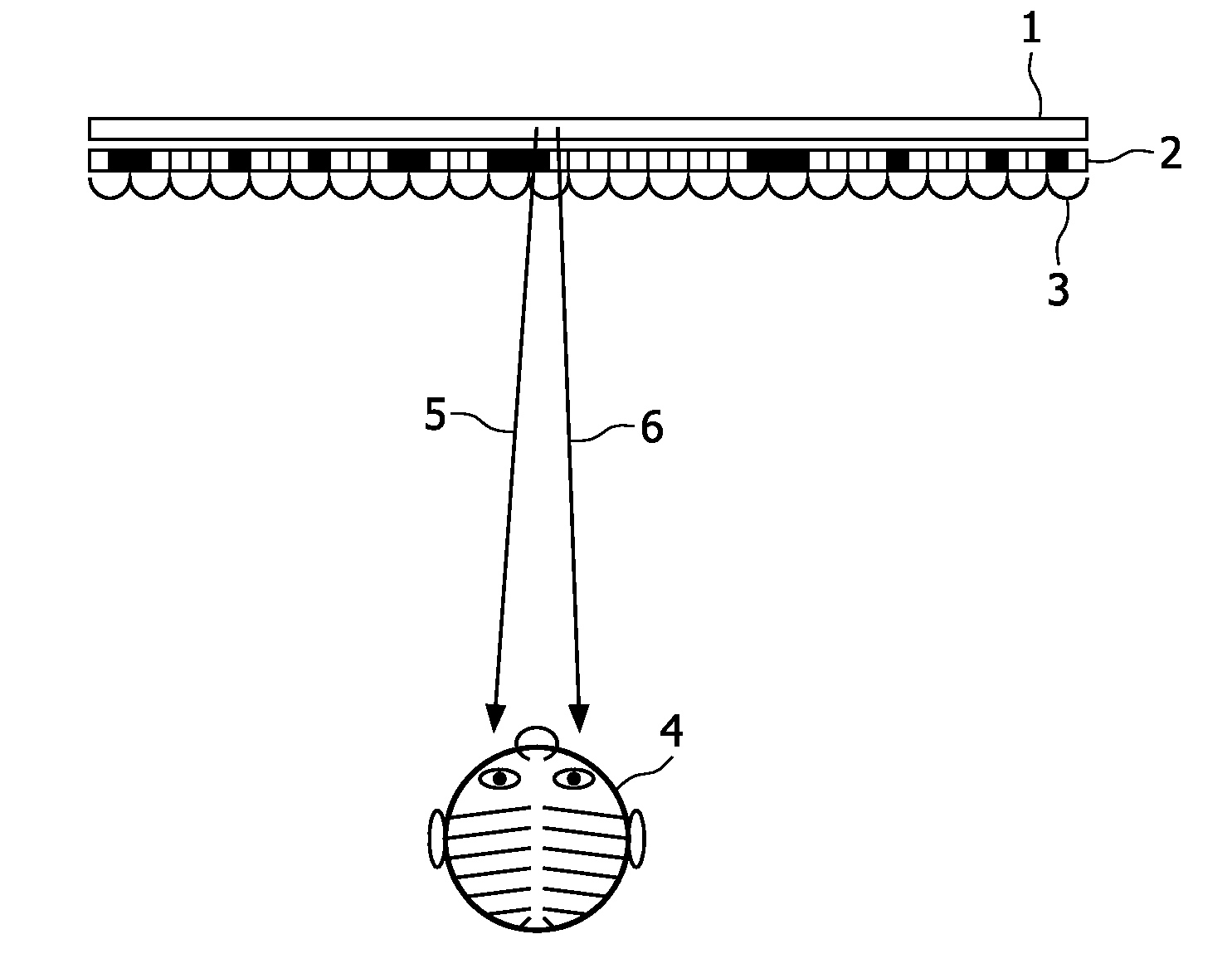
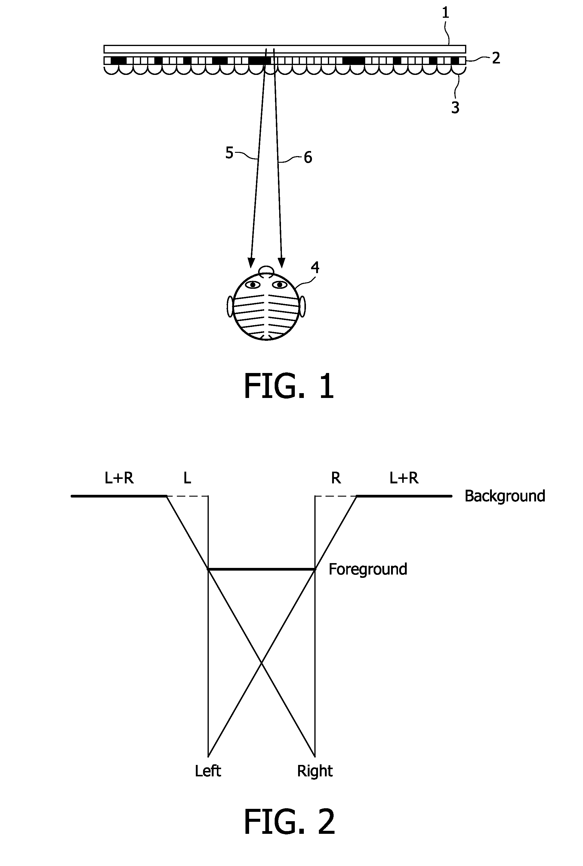
[0070]FIG. 1 illustrates the basic principle of a type of auto-stereoscopic display device. The display device comprises a lenticular screen 3 for forming two stereo images 5 and 6. The vertical lines of two stereo images are (spatially) alternatingly displayed on, e.g., a spatial light modulator 2 (e.g. a LCD) with a backlight 1. Together the back light and the spatial light modulator form a pixel array. The lens structure of the lenticular screen 3 directs the stereo image to the appropriate eye of the viewer. In this example two images are shown. The invention is not restricted to a two view situation; in fact the more views are to be rendered, the more information is to be encoded and the more the present invention is useful. However, for ease of explanation, in FIG. 1 a two view situation is depicted. It is noted, that an important advantage of the invention is that multiple (types of) layers also allow wider sideview capabilities and / or large depth range displays since it allo...


PUM


Abstract

In a method for encoding and an encoder for a 3D video signal, a principal data layer, a depth map for the principal data layers and further data layers are encoded. Several data layers are combined in one or more common data layers by moving data segments such as data blocks from data layers of origin into common data layers and keeping record of the shift in an additional data stream.

Description

FIELD OF THE INVENTION[0001]The invention relates to the field of video encoding and decoding. It presents a method, system and encoder for encoding a 3D video signal. The invention also relates to a method, system and decoder for decoding a 3D video signal. The invention also relates to an encoded 3D video signal.BACKGROUND OF THE INVENTION[0002]Recently there has been much interest in providing 3-D images on 3-D image displays. It is believed that 3-D imaging will be, after color imaging, the next great innovation in imaging. We are now at the advent of introduction of 3D displays for the consumer market.[0003]A 3-D display device usually has a display screen on which the images are displayed.[0004]Basically, a three dimensional impression can be created by using stereo pairs, i.e. two slightly different images directed at the two eyes of the viewer.[0005]There are several ways to produce stereo images. The images may be time multiplexed on a 2D display, but this requires that the...

Claims


Application Information

Patent Timeline
IPC IPC(8): H04N13/00
CPCH04N13/0048H04N13/0066H04N19/23H04N19/46H04N19/597H04N13/161H04N13/178H04N13/00
Inventor VAN DER HORST, JANBARENBRUG, BART GERARD BERNARDVAN DER HEIDEN, GERARDUS WILHEMUS THEODORUS
Owner KONINKLIJKE PHILIPS ELECTRONICS NV
Why Eureka
Try Eureka