
Layer thickness regulating member for regulating layer thickness of developer carried on developer carrying member and layer thickness regulating member manufacturing method

Active Publication Date: 2015-02-12
CANON KK
View PDF2 Cites 0 Cited by
  • Summary
  • Abstract
  • Description
  • Claims
  • Application Information

AI Technical Summary

Benefits of technology

The present invention is about a layer thickness regulating member that can reduce stress and distortion on the part that regulates layer thickness. The member is made using a metal mold. The technical effect of this invention is that it can provide a more precise and reliable way to control the thickness of layers in various applications such as manufacturing processes.

Problems solved by technology

In the developing device in JP-A 2012-247757, the layer thickness regulating member and the supporting members for supporting the layer thickness regulating member are provided as separate members, and therefore a component cost is expensive.
In a state in which the layer thickness regulating member is positionally adjusted relative to the developer carrying member, the layer thickness regulating member is fixed on the opposing member with the screws at a plurality of positions, and therefore an assembling cost is expensive.
However, in actuality, when the layer thickness regulating member provided with the layer thickness regulating portion was prototyped by the injection molding, the layer thickness regulating member caused distortion, so that it was turned out that layer thickness non-uniformity was generated with respect to the developer carried on the developer carrying member.

Method used


Image

  • Layer thickness regulating member for regulating layer thickness of developer carried on developer carrying member and layer thickness regulating member manufacturing method
  • Layer thickness regulating member for regulating layer thickness of developer carried on developer carrying member and layer thickness regulating member manufacturing method
  • Layer thickness regulating member for regulating layer thickness of developer carried on developer carrying member and layer thickness regulating member manufacturing method

Examples


embodiment 1

(Effect of Embodiment 1)

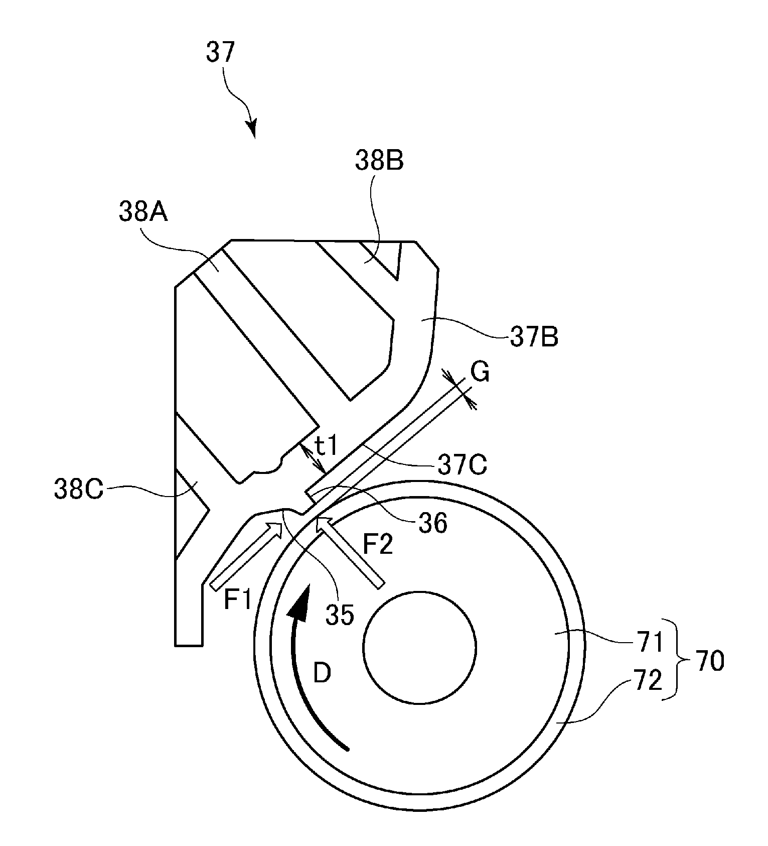
[0058]With respect to the sleeve holder frame 37 in Embodiment 1, from the viewpoints of reductions in weight and cost, the metal material is replaced with the resin material. The resin material is non-magnetic and is high in flexibility of the mold process, thus being preferable.

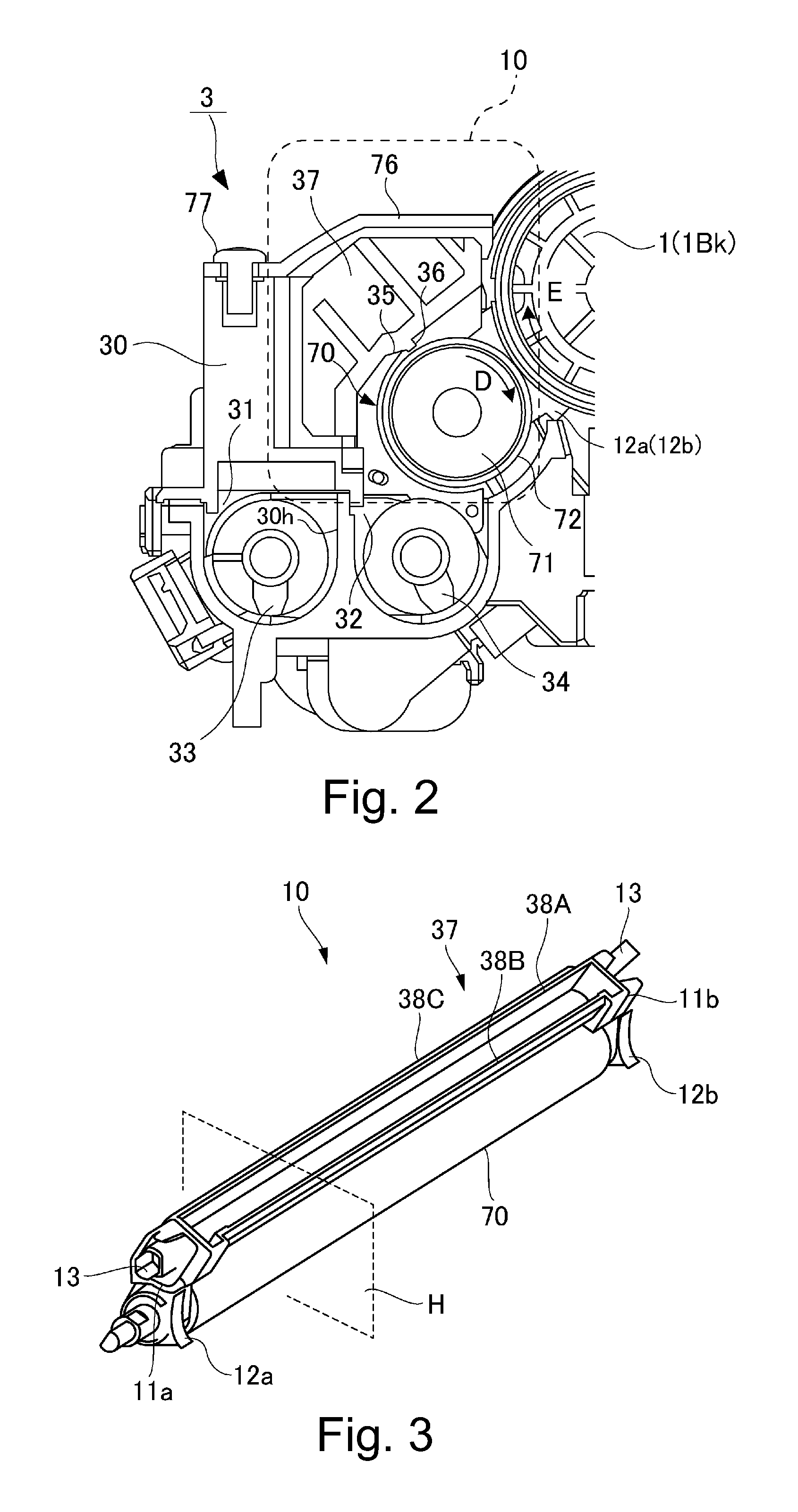
[0059]With respect to the sleeve holder frame in Embodiment 1, the developer rectifying portion 35 corresponding to the base member in Comparison Example 1 and the layer thickness regulating portion 36 corresponding to the layer thickness regulating member 73 in Comparison Example 1 are integrally constituted, so that a problem of inefficient adjustment in Comparison Example 1 is solved. The integral constitution between the developer rectifying portion 35 and the layer thickness regulating portion 36 easily ensures large geometrical moment of inertia also in terms of rigidity.

[0060]With respect to the sleeve holder frame 37 in Embodiment 1, the developer rectifying portion and the l...

embodiment 2

(Effect of Embodiment 2)

[0077]With respect to the sleeve holder frame 37, even when flexure due to a load and warpage due to thermal deformation are included, it becomes possible to straightness of the layer thickness regulating portion 36 can be suppressed to 20-30 μm or less, so that it was possible to provide a developing device capable of providing a stable image density.

[0078]The sleeve holder frame in this embodiment has a shape such that the same cross-sectional configuration is continued over an entire region with respect to a rotational axis direction of the developing sleeve 70, and therefore a distribution of thermal stress with a change in operation environment (temperature and humidity) becomes uniform.

[0079]The sleeve holder frame 37 in this embodiment is not provided with the thick reinforcing rib, and geometrical moment of inertia can be sufficiently ensured, and therefore it is possible to ensure rigidity against forces F1 and F2.

[0080]Incidentally, in actuality, th...

embodiment 3

[0081]The present invention can be carried out also in other embodiments in which a part or all of constituent elements in the above-described embodiments are replaced with alternative constituent elements thereof so long as the layer thickness regulating member formed integrally with the layer thickness regulating portion is pushed out (ejected) from the split mold provided in a side opposite from the layer thickness regulating portion. When the developing device and the process cartridge include the toner regulating member formed integrally with the layer thickness regulating portion, the present invention is capable of being carried out.

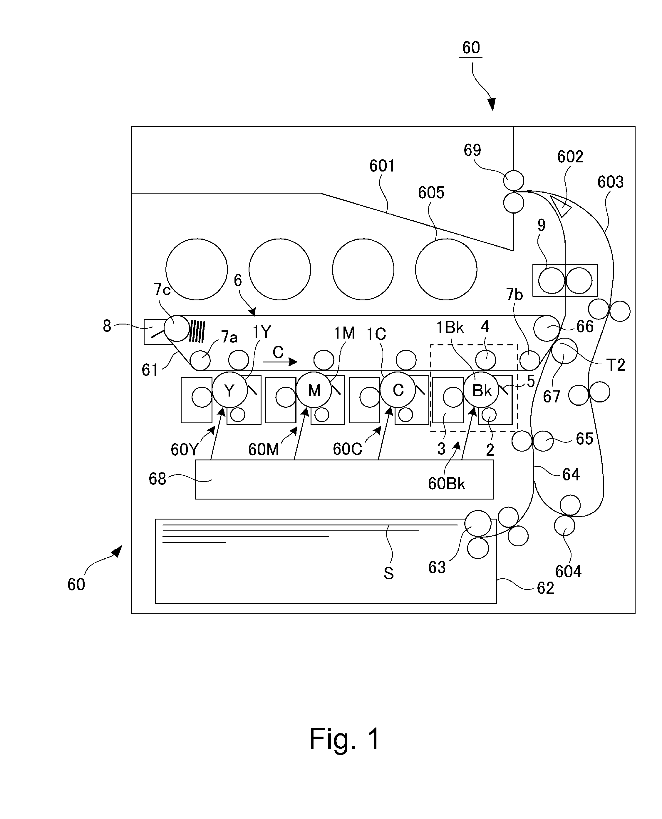
[0082]In Embodiments 1 to 3, the case of the developing device is described as an example, but a similar effect can be obtained even when a process cartridge prepared by integrally assembling the image forming portion 60Bk (FIG. 4) including the developing device into a unit and being made detachably mountable to the image forming apparatus is use...


PUM

PropertyMeasurementUnit
Thicknessaaaaaaaaaa

Abstract

A layer thickness regulating member includes: an opposing portion having an opposing surface to a peripheral surface of a developer carrying member; and a layer thickness regulating portion, projected from the opposing surface toward the developer carrying member, for regulating a layer thickness of a developer carried on the developer carrying member. The layer thickness regulating portion is integrally molded with the opposing portion. The layer thickness regulating member is, after being molded in a metal mold, separated by being pushed from a side opposite from the opposing portion of the layer thickness regulating member when the layer thickness regulating member is separated from the metal mold.

Description

FIELD OF THE INVENTION AND RELATED ART[0001]The present invention relates to a layer thickness regulating member prepared by integrally molding, with a resin material, an opposing portion having an opposing surface to a peripheral surface of a developer carrying member and a layer thickness regulating portion for regulating a layer thickness of a developer, and relates to a layer thickness regulating member manufacturing method using injection molding.[0002]An image forming apparatus in which an electrostatic image formed on an image bearing member is developed by a developing device to form a toner image and then the formed toner image is transferred onto a recording material and is heated and pressed by a fixing device to form an image on the recording material has been widely used. The developing device regulates, by a layer thickness regulating member, the developer carried on a rotating developer carrying member to carry the developer in a uniform thickness on the developer car...

Claims


Application Information

Patent Timeline
IPC IPC(8): G03G15/08B29C45/40
CPCG03G15/0812B29K2101/00B29C2045/4078B29C45/40B29C45/1751B29K2101/12B29L2031/767
Inventor IWASAKI, HISANORI
Owner CANON KK
Learn More