Appliance for drying articles

a technology for drying articles and drying sheets, applied in drying, lighting and heating apparatus, furniture, etc., can solve problems such as microwave frequencies

Inactive Publication Date: 2015-02-19
WHIRLPOOL CORP
View PDF6 Cites 13 Cited by
  • Summary
  • Abstract
  • Description
  • Claims
  • Application Information

AI Technical Summary

Problems solved by technology

Microwave frequencies are typically applied for cooking food items and are considered undesirable for drying laundry articles because of the possible temporary runaway thermal effects random application of the waves in a traditional microwave.

Method used


Image

  • Appliance for drying articles
  • Appliance for drying articles
  • Appliance for drying articles

Examples


Embodiment Construction

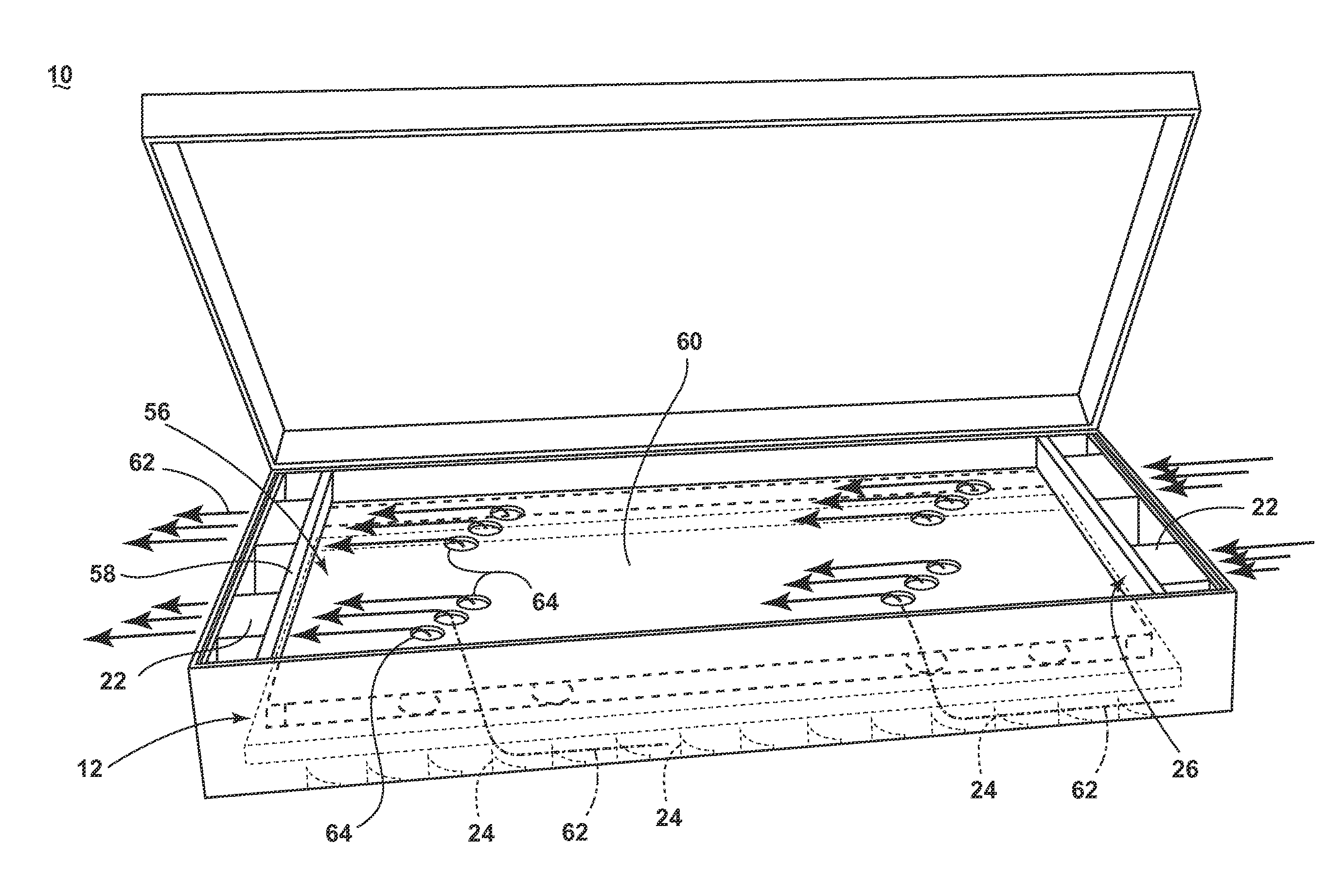
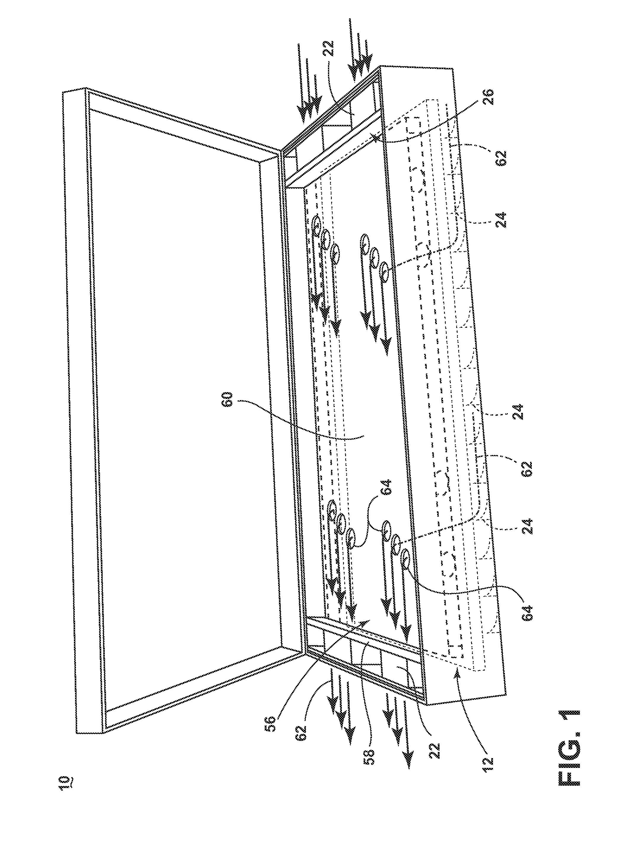
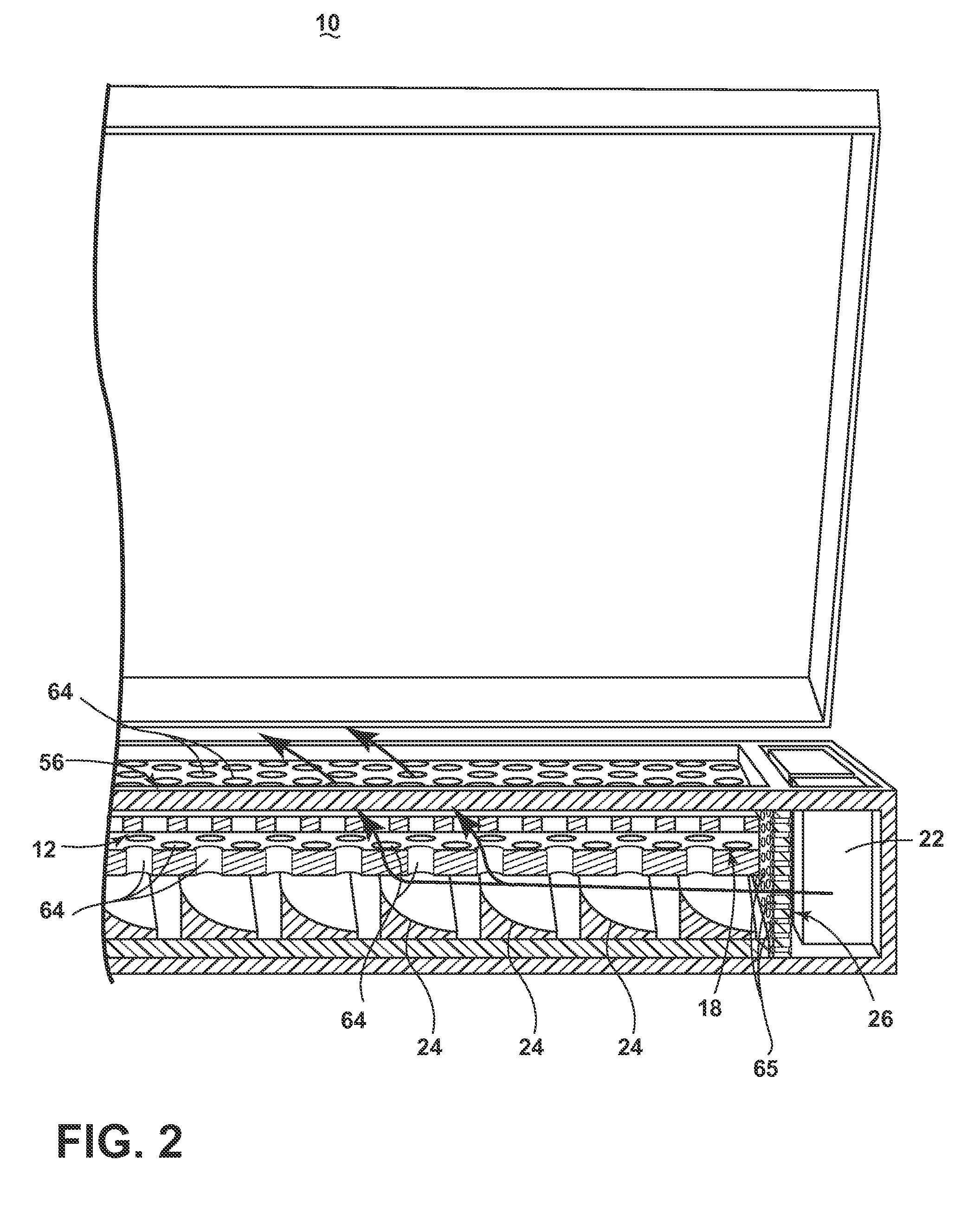
[0011]While this description may be primarily directed toward a laundry drying machine, the invention may be applicable in any environment using a radio frequency (RF) signal application to dehydrate any wet article.

[0012]FIG. 1 is a schematic illustration of an RF laundry drying appliance 10 according to the first embodiment of the invention for dehydrating one or more articles of laundry. As illustrated in FIGS. 1-3, the RF laundry drying appliance 10 includes an RF applicator 12 that includes conductive elements, such as an anode element 14 and an opposing cathode element 16; each element supported by a perforated body 18. The laundry drying appliance 10 additionally includes an RF generator 20 and one or more fans 22 arranged relative to the perforated body 18 to flow air through the perforated body 18. A perforated electromagnetic shield 26 may be placed between the fans 22 and the RF applicator 12. One or more baffles 24 may be arranged between the one or more fans 22 and the ...


PUM


Abstract

An RF laundry dryer includes, amongst other things, an RF generator, an RF applicator having a perforated body supporting anode and cathode elements, a fan arranged relative to the perforated body to flow or draw air through the perforated body and an electromagnetic shield protecting the fan from the e-field. Both anode and cathode elements are operably coupled to the RF generator to generate an e-field between the anode and cathode upon the energizing of the RF generator.

Description

BACKGROUND OF THE INVENTION[0001]Dielectric heating is the process in which a high-frequency alternating electric field heats a dielectric material, such as water molecules. At higher frequencies, this heating is caused by molecular dipole rotation within the dielectric material, while at lower frequencies in conductive fluids, other mechanisms such as ion-drag are more important in generating thermal energy.[0002]Microwave frequencies are typically applied for cooking food items and are considered undesirable for drying laundry articles because of the possible temporary runaway thermal effects random application of the waves in a traditional microwave. Radio frequencies and their corresponding controlled and contained e-field are typically used for drying of textiles.[0003]When applying an RF electronic field (e-field) to a wet article, such as a clothing material, the e-field may cause the water molecules within the e-field to dielectrically heat, generating thermal energy that ef...

Claims


Application Information

Patent Timeline
Patent Type & Authority Applications(United States)
IPC IPC(8): F26B3/34
CPCF26B3/343D06F58/20D06F58/266H05B6/54H05B6/62
Inventor HERMAN, MARK L.PETERMAN, GARRY L.
Owner WHIRLPOOL CORP
Why Eureka
Try Eureka