Aortic occluder with tensioned balloons

a technology of balloons and occluders, which is applied in the field of aortic occluders with pretensioned balloons, to achieve the effect of improving cerebral perfusion and better bearing

Inactive Publication Date: 2015-02-19
ZOLL CIRCULATION
View PDF3 Cites 40 Cited by
  • Summary
  • Abstract
  • Description
  • Claims
  • Application Information

AI Technical Summary

Benefits of technology

[0003]Accordingly, a catheter includes an elongate member having proximal and distal ends and proximal and distal regions. A first expandable member is mounted on the distal region of the elongate member. The first expandable member is inflatable with fluid through at least one lumen in the elongate member to cause the expandable member to expand from an empty configuration to an expanded configuration. As disclosed in greater detail below, the first expandable member is disposed on the elongate member in tensio...

Problems solved by technology

As understood herein, a device that is positioned retrograde to blood flow in the aorta faces high fluid pressure against one or more of its opera...

Method used


Image

  • Aortic occluder with tensioned balloons
  • Aortic occluder with tensioned balloons
  • Aortic occluder with tensioned balloons

Examples


Embodiment Construction

[0022]For convenience, portions of the above-incorporated patent are first discussed.

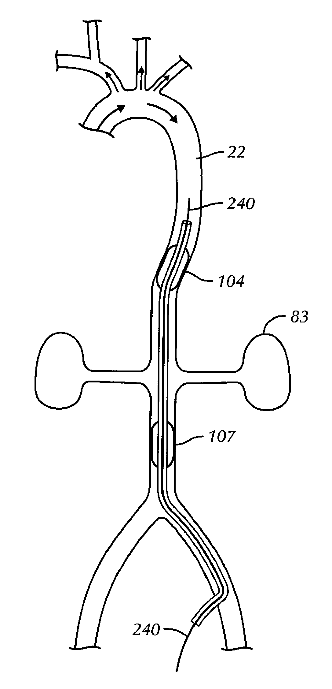
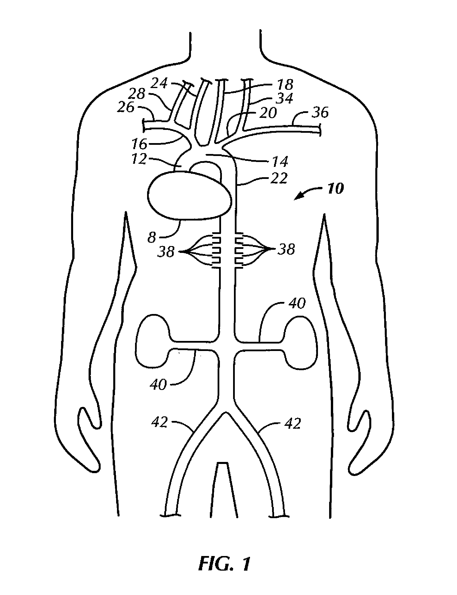
[0023]Referring initially to FIG. 1, during systole, oxygenated blood leaving a patient's heart 8 enters the aorta 10, which includes the ascending aorta 12, aortic arch 14, and descending aorta 22. The aortic arch gives rise to the brachiocephalic trunk 16, left common carotid artery 18, and left subclavian artery 20. The brachiocephalic trunk branches into the right common carotid artery 24 and right subclavian artery 26. The right and left subclavian arteries, respectively, give rise to the right vertebral artery 28 and left vertebral artery 34. The descending aorta gives rise to a multitude of arteries, including lumbar (i.e., spinal) arteries 38, which perfuse the spinal cord, renal arteries 40, which perfuse the kidneys, and femoral arteries 42, which perfuse the lower extremities.

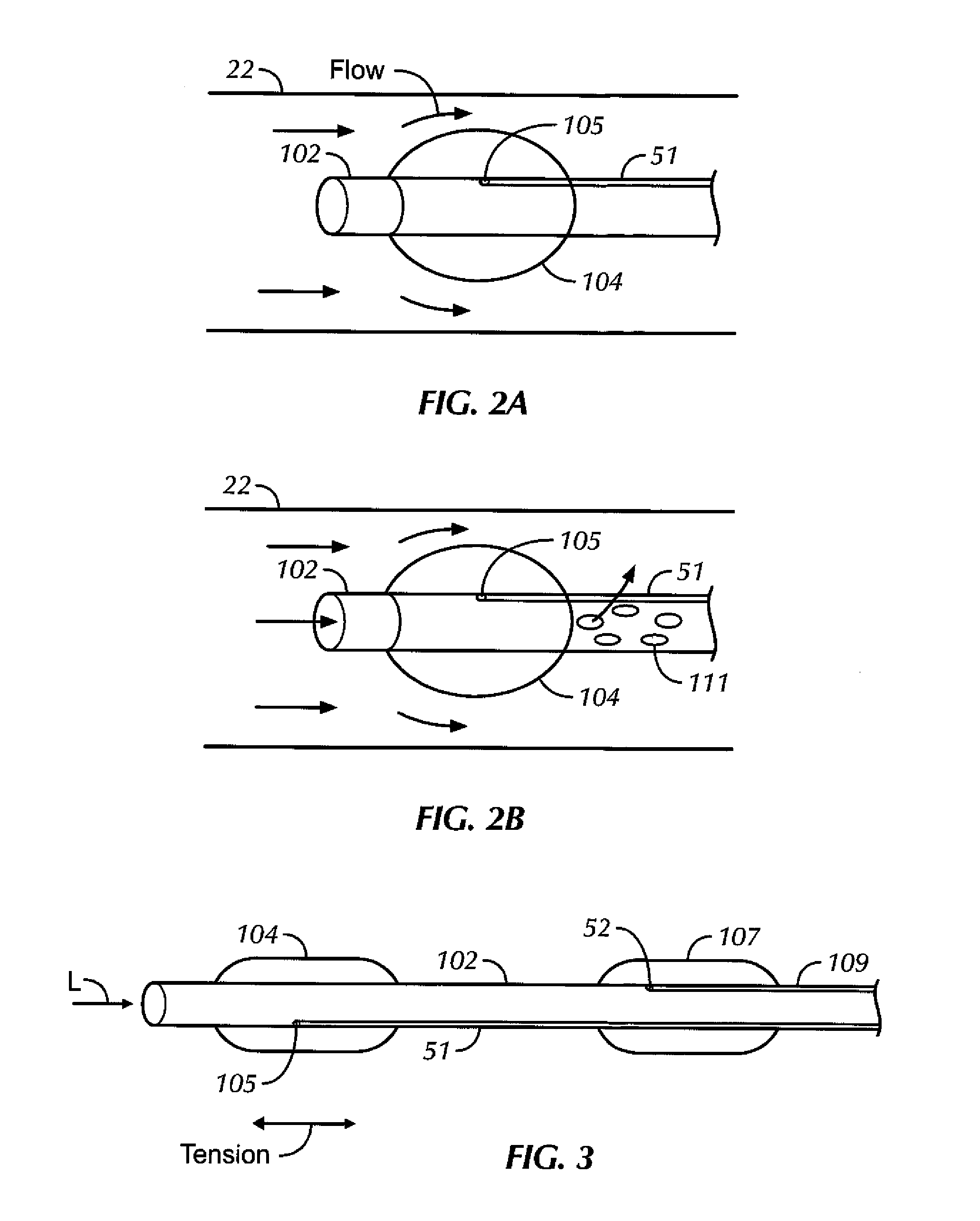
[0024]In one embodiment as shown in FIG. 2A, an aortic occluder or obstruction device includes an elongate cathete...


PUM

PropertyMeasurementUnit
Luminous fluxaaaaaaaaaa
Stabilityaaaaaaaaaa
Tensionaaaaaaaaaa

Abstract

An aortic occluder catheter with expandable balloons for increasing cerebral blood blow has one or more balloons on a catheter shaft. To assist the balloon in bearing up against arterial blood flow while positioned retrograde in the aorta, the balloon is bonded to the catheter shaft in tension.

Description

I. FIELD OF THE INVENTION[0001]The present application relates generally to aortic occluders with pre-tensioned balloons.II. BACKGROUND OF THE INVENTION[0002]In the present assignee's U.S. Pat. No. 6,743,196, incorporated herein by reference, devices and methods are disclosed for partially or completely occluding the aorta temporarily to augment cerebral perfusion. As understood herein, a device that is positioned retrograde to blood flow in the aorta faces high fluid pressure against one or more of its operative components, presenting challenges that otherwise would not be presented were the device to be located in a vessel of less harsh fluid flow dynamics.SUMMARY OF THE INVENTION[0003]Accordingly, a catheter includes an elongate member having proximal and distal ends and proximal and distal regions. A first expandable member is mounted on the distal region of the elongate member. The first expandable member is inflatable with fluid through at least one lumen in the elongate membe...

Claims


Application Information

Patent Timeline
IPC IPC(8): A61B17/12B32B37/14A61B5/0215
CPCA61B17/12109A61B17/12036A61B17/12045A61B17/12136B32B2535/00A61B5/0215B32B37/142A61B2017/22054A61B2017/00526A61B17/1219A61M25/0102A61M25/1011A61M25/1034A61M2025/1052A61M2025/1095
Inventor KRAVIK, RICHARD C.GREENBERG, JAMESXIONG, CRYSTALLEE, NAO
Owner ZOLL CIRCULATION
Why Eureka
Try Eureka