Method and circuit arrangement for limiting peak currents and the slope of the current edges

a technology of current edge slope and circuit arrangement, which is applied in the direction of motor/generator/converter stopper, dynamo-electric converter control, braking system, etc., can solve the problems of limiting the safety and comfort of the vehicle occupants, intermittent drop in supply voltage, and severe loading of the entire vehicle onboard power supply system

Active Publication Date: 2015-02-26
CONTINENTAL TEVES AG & CO OHG
View PDF16 Cites 0 Cited by
  • Summary
  • Abstract
  • Description
  • Claims
  • Application Information

AI Technical Summary

Benefits of technology

[0019]The advantage is that at functional fallback levels of the motor vehicle brake system or in...

Problems solved by technology

This applies particularly to electric motors in a motor vehicle brake installation, the high starting currents of which can result in severe loading of the entire vehicle onboard power supply system and in an intermittent drop in the supply voltage.
This can in turn affect the functionality of other vehicle components and hence restrict safety and comfort for the vehicle occupants.
Systems according to the prior art no longer meet the present demands on the limitation of peak currents, particularly on the basis of the charge quantity provided by the voltage source and also the maximum slope of the current edges.
It is not possible for the PWM actuation frequency to be increased arbitrarily, since the high computation workload of the microcontroller means that alteration of the duty cycle by the control software results in almost no further functions being abl...

Method used


Image

  • Method and circuit arrangement for limiting peak currents and the slope of the current edges
  • Method and circuit arrangement for limiting peak currents and the slope of the current edges
  • Method and circuit arrangement for limiting peak currents and the slope of the current edges

Examples


Embodiment Construction

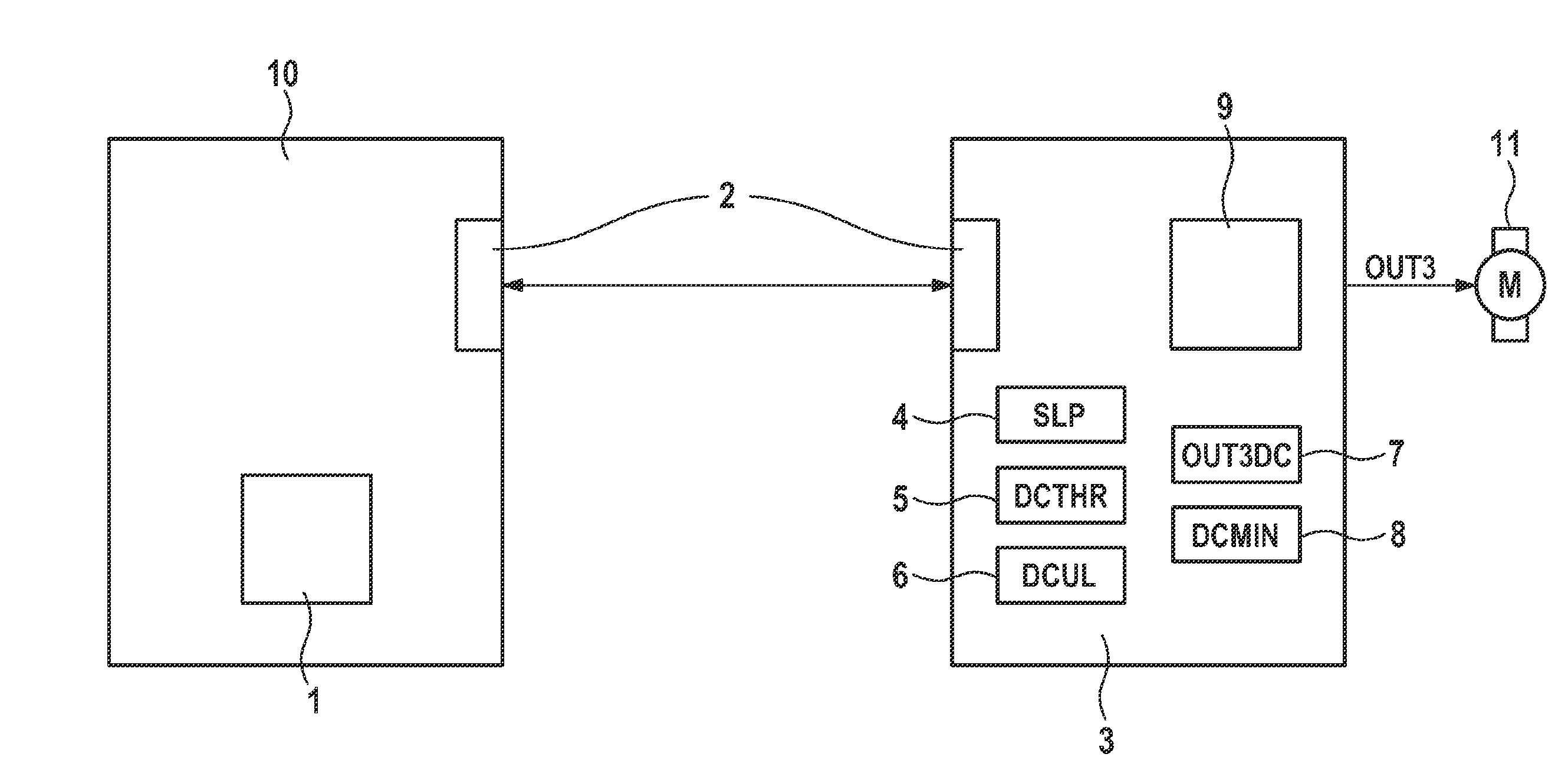
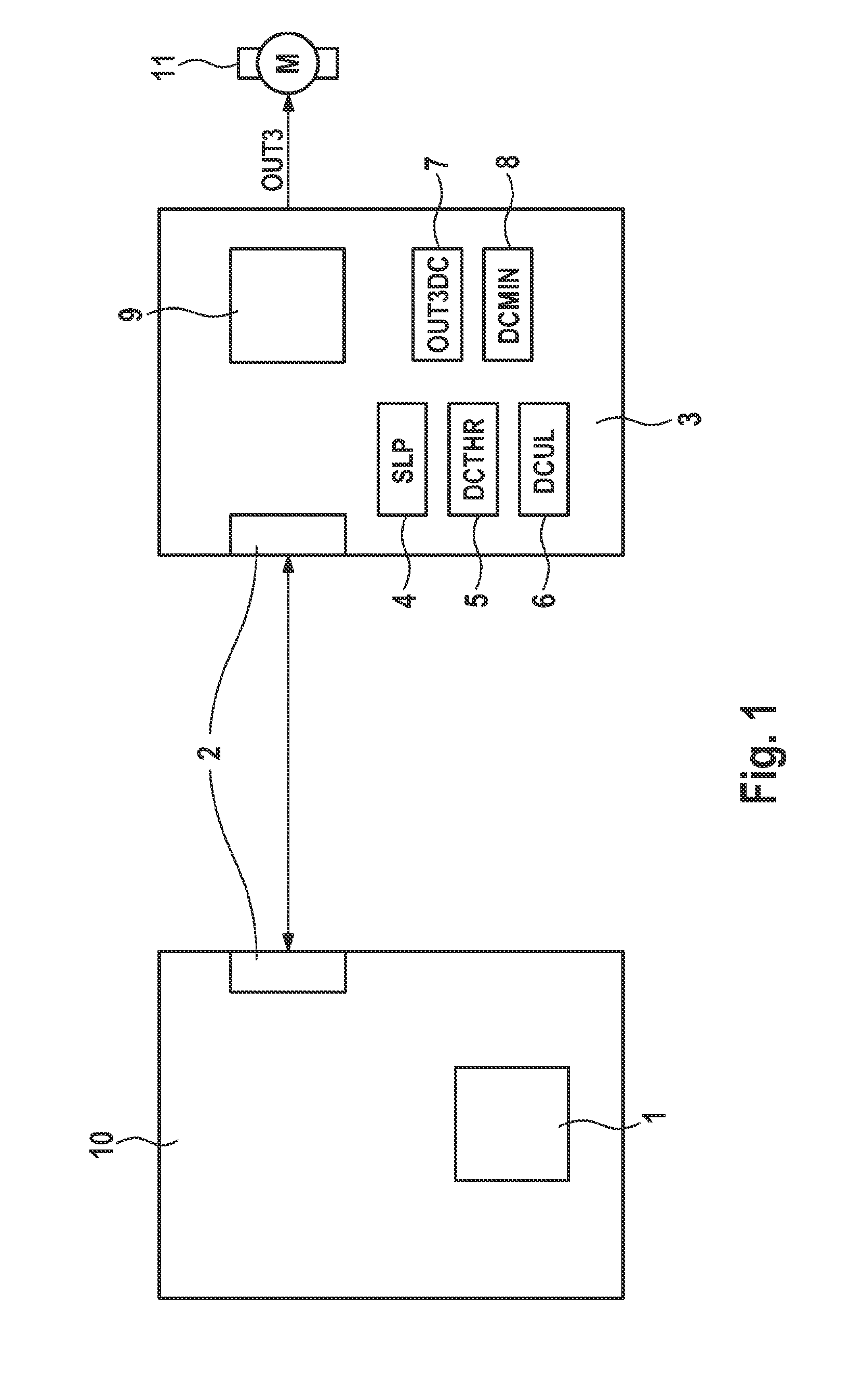
[0027]FIG. 1 shows a schematic diagram of the inventive electronic circuit arrangement, wherein the microcontroller unit (MCU) 10 and the hardware module (PCU) 3 communicate via the SPI bus system 2. The MCU 10 comprises the microcontroller 1, which executes calculations for the brake control system. The SPI bus system 2 is used to store the values calculated in this manner, the setpoint duty cycle OUT3DC, the slope value SLP, the first duty cycle threshold value DCTHR, the second duty cycle threshold value DCUL and the minimum value of the duty cycle DCMIN, in the logic registers 4 to 8 of the PCU 3. The PCU 3 performs the actuation for the electric motor 11 by means of the hardware logic unit 9, which accesses the logic registers 4 to 8. The electric motor is actuated in a manner that is known per se by means of the field effect transistor, the gate of which is in turn actuated by the hardware logic unit 9, this not being shown explicitly.

[0028]The circuit arrangement shown in FIG...


PUM


Abstract

A method for limiting peak currents, particularly depending on a charge quantity provided by a voltage source, and the maximum pitch of the current flanks of an electric motor for an electrohydraulic motor vehicle brake system, particularly a pump motor, controlled by pulse width modulation, wherein a change to an actual duty cycle of the PWM is made by a first duty cycle of the PWM on a second duty cycle at runtime, wherein the change takes place according to a positive or negative pitch value calculated and/or changeable at runtime. The invention further describes an electronic circuit arrangement for the implementation of a method for limiting peak currents and the maximum pitch of current flanks.

Description

CROSS REFERENCE TO RELATED APPLICATIONS[0001]This application is the U.S. National Stage Application of PCT International Application No. PCT / EP2013 / 054385, filed Mar. 5, 2013, which claims priority to German Patent Application No. 10 2012 203 558.3, filed Mar. 7, 2012 and German patent Application No. 10 2012 213 874.9, filed Aug. 6, 2012, the contents of such applications being incorporated by reference herein.FIELD OF THE INVENTION[0002]The present invention relates to a method for limiting peak currents and also the maximum slope of the current edges and also to a circuit arrangement.BACKGROUND OF THE INVENTION[0003]In order to prevent malfunctions in the increasing number of electronic components or in the power supply in the vehicle and related safety or comfort restrictions for the vehicle occupant, the demands on electrical components to keep the power draw from the vehicle onboard power supply system within defined limits are increasing. This applies particularly to electri...

Claims


Application Information

Patent Timeline
IPC IPC(8): H02P29/02B60T13/66
CPCB60T13/662H02P29/02B60T8/404B60T8/405H02P29/032
Inventor HEINZ, MICHAMICHEL, FRANK
Owner CONTINENTAL TEVES AG & CO OHG
Why Eureka
Try Eureka