Display method through a head mounted device

a display method and head mounted technology, applied in the field of user interaction with target devices, can solve the problem that the probability of non-intentional validation of control operations is very low, and achieve the effect of low probability

Active Publication Date: 2015-02-26
INTERDIGITAL CE PATENT HLDG
View PDF0 Cites 9 Cited by
  • Summary
  • Abstract
  • Description
  • Claims
  • Application Information

AI Technical Summary

Benefits of technology

[0012]a step of detecting if said selected first area and said second area are at least partially overlapping a same dedicated area associated to a control operation to be performed by said target device; and in case of detection of an occurrence of said at least partially overlapping, said method further comprising a step of valida

Problems solved by technology

Indeed, with such method, a non-intentional validation of

Method used


Image

  • Display method through a head mounted device
  • Display method through a head mounted device
  • Display method through a head mounted device

Examples


Embodiment Construction

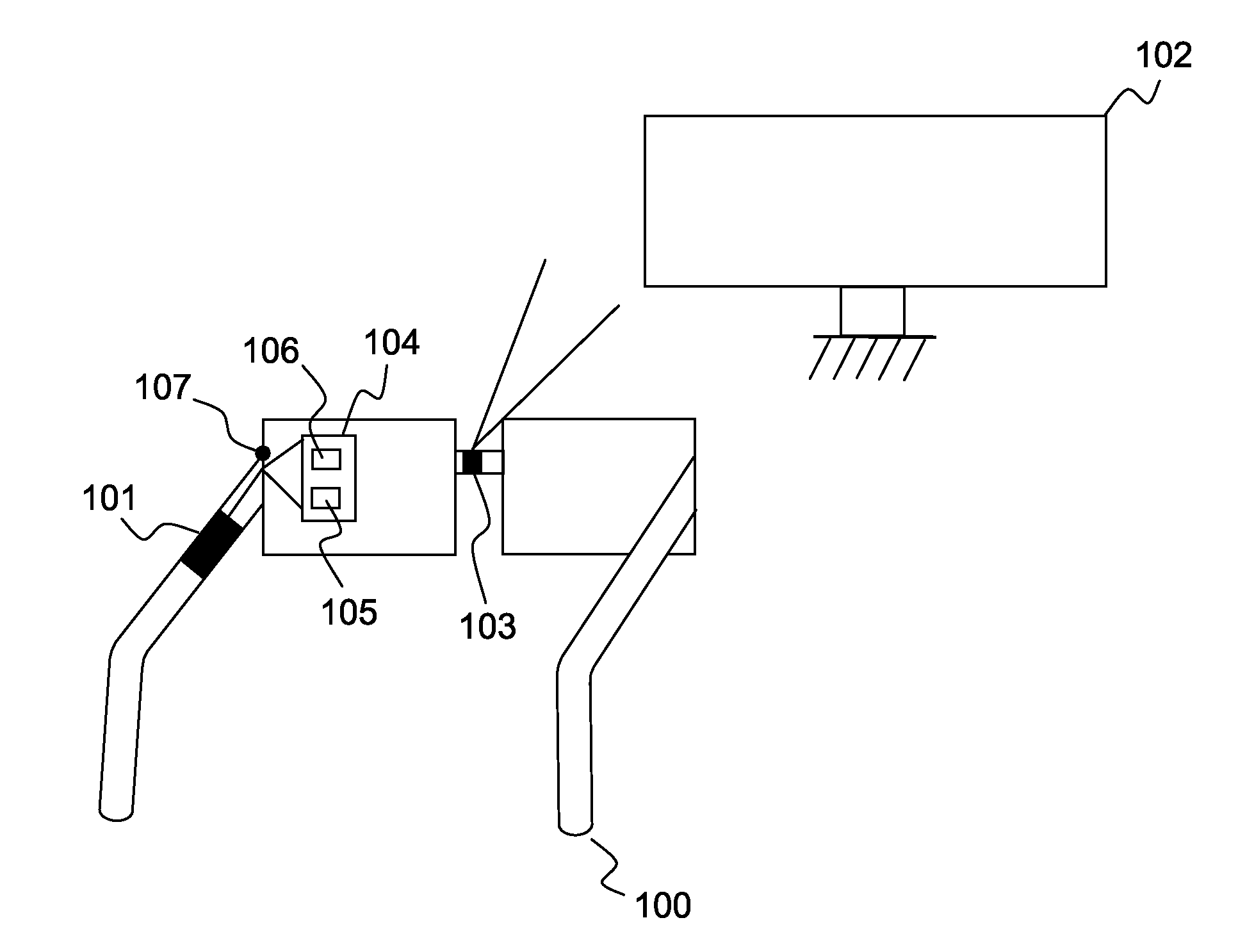
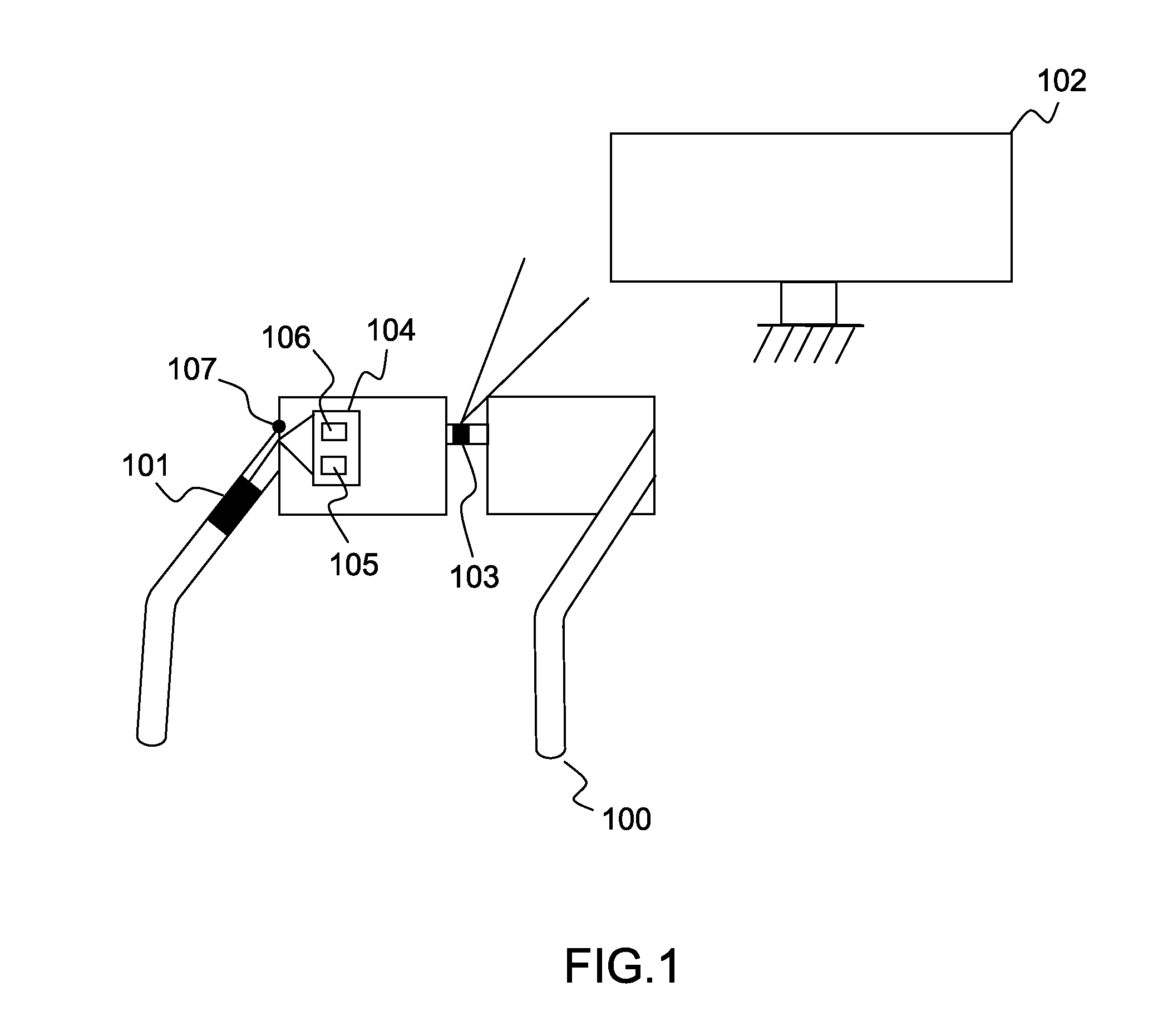
[0035]FIG. 1 presents a head mounted device according to one embodiment of the disclosure.

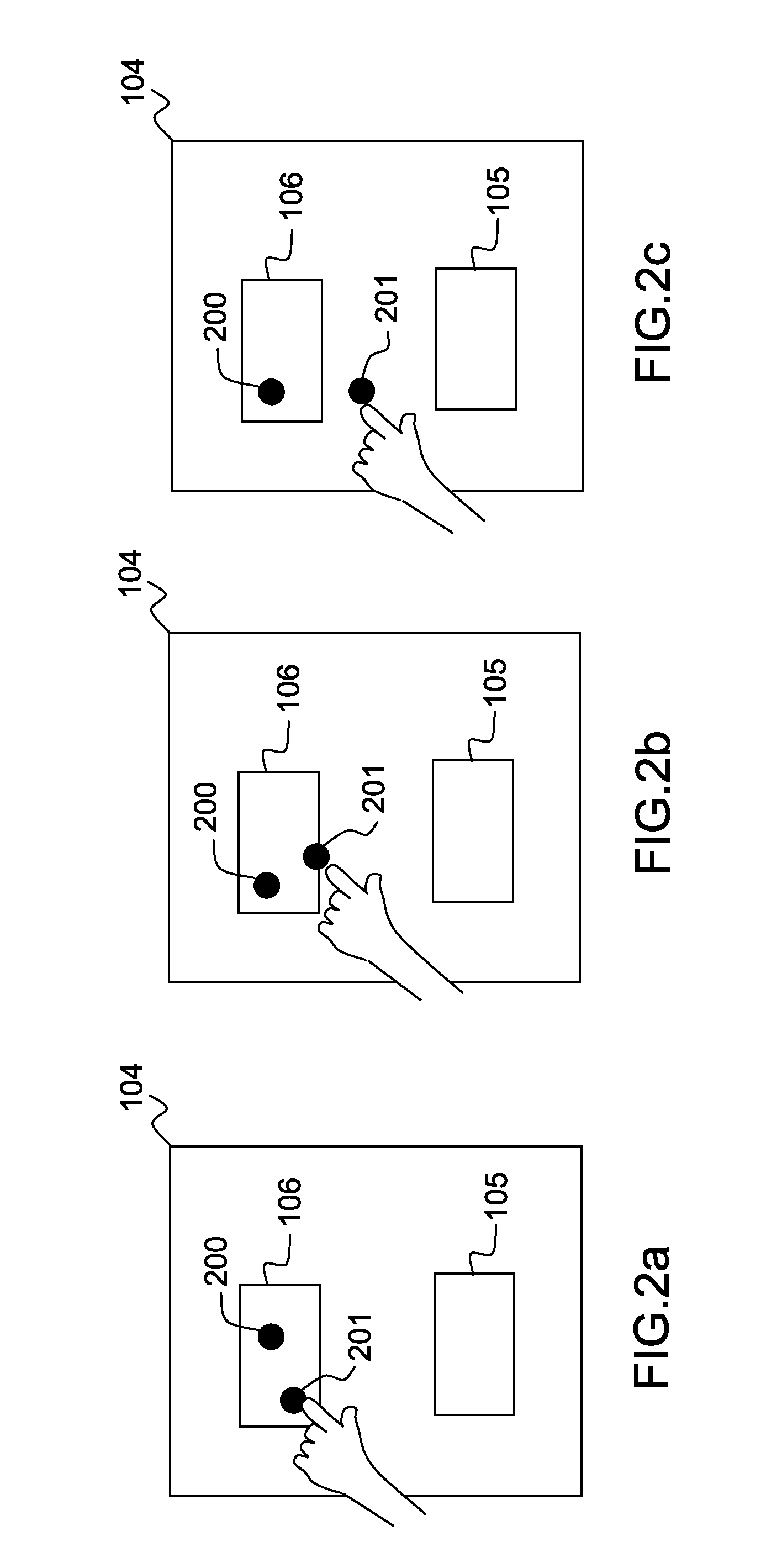
[0036]More precisely, in such embodiment, an head mounted device, referenced 100, comprises two glasses, and an electronic device, referenced 101, (an example of such device is detailed in the FIG. 4), that can generate or handle a signal to be displayed to a user, a sensor referenced 103 that can detect a target device for which an action is to be done, and another sensor referenced 107, that can detect the gaze of the user wearing such head mounted device. In one embodiment, the displayed signal is directly projected in the retina of the user. In another embodiment, the displayed signal is projected within one of the two glasses. Such signal to be displayed can represent a virtual control interface, referenced 104, that enables to control a target device, as for example a TV set, referenced 102.

[0037]When the user moves his head in the direction of the TV set, the sensor 103 detects (for exam...


PUM


Abstract

In one embodiment, it is proposed a method for validating a control operation to be performed by a target device through a virtual control interface, the virtual control interface being displayed by a head mounted device of a user. The method is remarkable in that it comprises:
    • a step of detecting a selection instruction of a first area, delivering a selected first area;
    • a step of detecting a position of gaze of the user, delivering a second area within the virtual control interface;
    • a step of detecting if the selected first area and the second area are at least partially overlapping a same dedicated area associated to a control operation to be performed by said target device; and in case of detection of an occurrence of said at least partially overlapping, said method further comprising a step of validating the control operation.

Description

FIELD OF THE DISCLOSURE[0001]The disclosure relates to user's interaction with target devices. More precisely, the disclosure is to be used in the context where a person uses a device named a wearable computer with a head-mounted display (also named as a head display device), such as for example see trough glasses, and interacts with such target devices.BACKGROUND OF THE DISCLOSURE[0002]This section is intended to introduce the reader to various aspects of art, which may be related to various aspects of the present disclosure that are described and / or claimed below. This discussion is believed to be helpful in providing the reader with background information to facilitate a better understanding of the various aspects of the present disclosure. Accordingly, it should be understood that these statements are to be read in this light, and not as admissions of prior art.[0003]Nowadays, it is possible to control devices by the use of a control user interface displayed by a wearable comput...

Claims


Application Information

Patent Timeline
IPC IPC(8): G06F3/0346G02B27/00G02B27/01
CPCG06F3/0346G02B27/017G02B27/0101G02B2027/0178G02B2027/0138G02B2027/014G02B27/0093G06F3/012G06F3/013G06F3/017G06F3/0304G06F3/0488G06F3/167G06F2203/0382G06F2203/0381
Inventor ORHAND, ANITADOYEN, DIDIERVIAL, JEAN-FRANCOIS
Owner INTERDIGITAL CE PATENT HLDG
Why Eureka
Try Eureka