Environmentally sealed cable breakout assemblies

a technology of environment sealing and cable breakout, which is applied in the direction of cables, insulated conductors, instruments, etc., can solve the problems of large number of cables, unfavorable tower space occupation, and the loss of signal and power consumption

Active Publication Date: 2015-02-26
HUBERSUHNER AG
View PDF2 Cites 22 Cited by
  • Summary
  • Abstract
  • Description
  • Claims
  • Application Information

AI Technical Summary

Benefits of technology

[0007]Accordingly, the present invention provides the ability to provide a single power feeder cable and associated assembly that can provide power to a number of individual amplifiers at the top of a radio (cell) tower. In addition, the invention offers the ability to exchange data with the RRH in a single cable. The construction according to the present invention reduces the number of cables extending up the tower and cable pulls, and reduces the number of connections required. At the top of the tower, a single feeder cable interfaces with a number of radio leads for amplifiers within an environmentally sealed container or through sealed, flexible conduits.
[0010]The two open ends of the respective portions of the cable breakout enclosure are threaded together and sealed with a permanent bond adhesive, suitable examples of which include, but are not limited to, thread locker, adhesives, water blocks and gels. Thereby, the cable breakout enclosure provides further environmental protection and added mechanical stability for the cable breakout, and protects the cable breakout from experiencing potentially harmful flexing and reduces weakening or detachment of the spliced joints, for example. Three levels of sealing are thus provided in view of the importance of preventing moisture and contaminants from entering the cable breakout in order to prevent shorts and broken contacts, etc., so as to improve the performance and reliability of the cable breakout and the overall cell performance.
[0011]The improved performance and reliability of the cable breakout assembly according to the present invention is also a cost effective solution, in that, for example, using a single feeder cable reduces installation costs (fewer cable pulls, fewer hoist grips, ground straps and support blocks) and tower fees (fewer cables) and, since service is needed less often, if at all, service and maintenance costs are reduced or prevented. In addition, the cable breakout assembly according to this embodiment of the present invention also enables the feeder cable to be supplied on reels at longer lengths (e.g., 200+m), and provides a “plug and play” feature for direct deployment, with no tools required, which reduces the hardware and installation time.
[0013]According to another embodiment of the present invention, cable breakout structure is provided that also facilitates cable breakout from a single feeder cable running up the tower to multiple radio lead cables positioned at the top. The cable breakout according to this embodiment of the present invention is hereinafter referred to as a splice puck, and provides further advantages in that the size of the breakout is reduced, crimps are eliminated, the assembly is simplified and costs can be further reduced without sacrificing performance and reliability. In addition, a secure level of environmental protection is provided without the need for additional shrink tubes or boots or enclosure structures.
[0014]The splice puck is a unitary structure having a central through bore and including three distinct portions, a threaded feeder cable side, a centre conduit portion, and a threaded cable breakout side. The outer diameter of the threaded feeder cable side and the threaded cable breakout side are substantially the same, whereas the centre conduit portion has a smaller outer diameter and includes four flat sides (see FIGS. 7A and 7B), and since the outer shape of the splice puck is that of an “H”, the shape facilitates the ability to easily and sufficiently secure the splice puck using a pipe clamp, for example, at the top of the tower. Additionally, the four flat surfaces at the centre of the centre conductor provide a necessary holding surface for use in connection with a wrench during assembly.
[0023]A cable breakout assembly according to the present invention normally comprises a hybrid cable assembly which preferably has factory terminated fibers and an integrated shielded power cable. It becomes possible to install the cable breakout assembly by plug and play installation whereby—in difference to the prior art—no field termination / wrapping / or other preparation is necessary.

Problems solved by technology

However, there has been a problem with respect to the signal losses experienced and the power consumption involved in this configuration.
This construction presents problems in that a larger number of cables are required to run up the tower, which involves a number of cable pulls, and also undesirably occupies space on the tower.
This is especially costly when one considers that the installation costs are increased with more cables, because installers typically charge per cable pull required, and the overall costs are increased because tower owners may charge by the number of cables.
The added weight of numerous cables can be a drawback, as well as wind loading issues related to multiple-cable configurations on the tower.
In addition, the use of more components introduces the potential for increased installation steps, and more maintenance issues associated with more connections.

Method used


Image

  • Environmentally sealed cable breakout assemblies
  • Environmentally sealed cable breakout assemblies
  • Environmentally sealed cable breakout assemblies

Examples


first embodiment

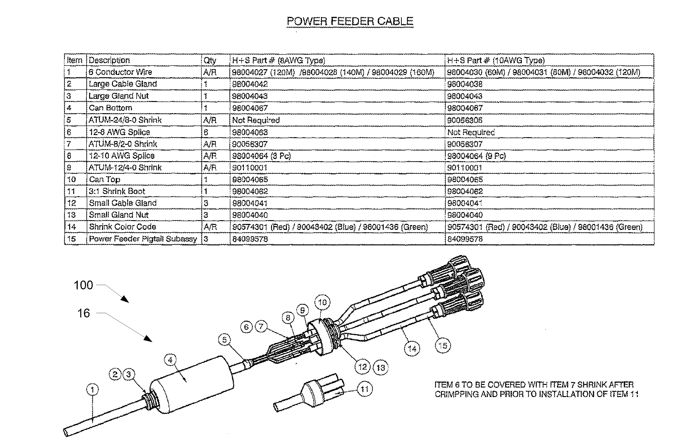
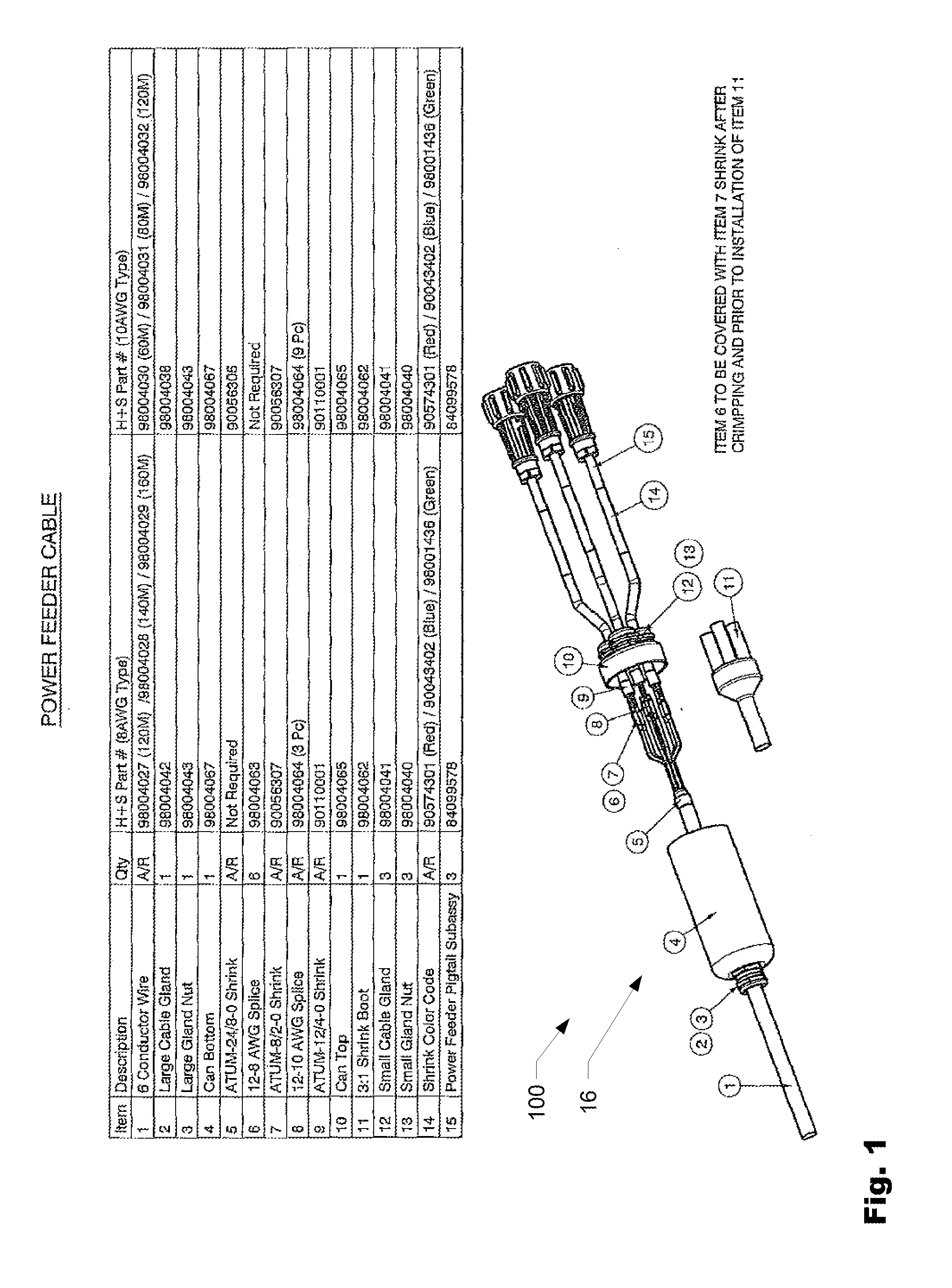
[0040]FIG. 1 is an exploded, perspective assembly view of a cable breakout assembly 100 according to the present invention. The cable breakout assembly 100 includes a feeder conductor wire 1, which is fed through a large cable gland 2 of a large cable nut 3 extending from the closed end of the bottom portion 4 of the breakout enclosure (can) 16. The conductor feeder cable 1 is spliced, crimped with respective radio leads and sealed with shrink tubes, as denoted by numerals 5-9. A shrink boot 11 is fitted over the sealed splice / crimp area denoted by reference numbers 5-9. The crimped, sealed, radio lead sections are fed though three cable glands 12 of respective cable nuts 13 which extend from the closed end of the top portion 10 of the breakout enclosure (can). The respective radio leads are shrink sealed and color coded (as shown by reference numeral 14) and interface with the power feeder pigtail subassembly at reference numeral 15, which are fitted with respective connector devic...

second embodiment

[0044]FIG. 6 is a schematic side view of a cable breakout assembly referred to as a splice puck 200 according to the present invention, and FIGS. 7 A and 7B are cross-sectional views of the splice puck breakout assembly shown in FIG. 6. Suitable examples of materials for the splice puck 200 include, but are not limited to plastic, polycarbonate, nylon, aluminum, stainless steel and other suitable materials. The open cavity of the splice puck 200 can be filled with potting filler in a known manner, if desired, thereby eliminating the chance of environmental contamination.

[0045]The conductor cable 1 is fed through a cable nut 3 having a single port cable gland 2 and into the input end 201 of the splice puck 200. The conductors of the cable 1 are routed through the central conduit portion 202 of the splice puck 200 and into the breakout end 203 thereof, which is interfaced with a cable nut 204 having a multi-port cable gland 205. The conductors of the cable 1 pass through the respectiv...


PUM


Abstract

A cable breakout assembly is provided, including a feeder cable, a breakout structure having a first end threadedly engaged with a cable nut having a single-port cable gland through which the feeder cable extends, a central conduit which houses the sections of the feeder cable passing there through, and an opposed second end threadedly engaged with a cable nut having a multi-port cable gland, whose number of ports corresponds to the number of splices of the feeder cable. A plurality of environmentally sealed, flexible conduits are provided, each having a first end that interfaces with and extends from a respective port of the multi-port gland, and a second end adapted to interface with an external device, wherein each flexible conduit houses a respective spliced section of the feeder cable therein.

Description

CROSS REFERENCE TO RELATED APPLICATIONS[0001]This application is a continuation of U.S. application Ser. No. 13 / 817,589, filed Feb. 19, 2013, which in turn is the National Stage of International Application No. PCT / EP2011 / 054276, filed Mar. 21, 2011, which in turn claims the benefit of Provisional Application No. 61 / 384,827, filed Sep. 21, 2010, the entireties of which are incorporated herein by reference.FIELD OF THE INVENTION[0002]The present invention relates to a cable breakout assembly remote radio heads (RRH).BACKGROUND OF THE INVENTION[0003]Radio heads and other equipment for amplifying and transmitting signals from antenna towers were traditionally positioned at the base of the tower in order to better facilitate the installation and maintenance thereof. However, there has been a problem with respect to the signal losses experienced and the power consumption involved in this configuration.[0004]So called remote radio heads (RRH) have become an important subsystem of todays n...

Claims


Application Information

Patent Timeline
Patent Type & Authority Applications(United States)
IPC IPC(8): G02B6/255H02G15/117
CPCH02G15/117H02G3/0406G02B6/4471G02B6/4472G02B6/4476G02B6/4416G02B6/545H01B7/0045H02G7/20
Inventor STRASSER, MARTINTORRI, DAVIDVEGA, AXELMAHMOOD, NASIRWHITCOMB, RANDALL
Owner HUBERSUHNER AG
Why Eureka
Try Eureka