Actuator with variable speed servo motor for redraw assembly

a servo motor and actuator technology, applied in the field of can bodymakers, can solve the problems of easy wear and tear of the mechanical linkage from the ram drive mechanism to the redrawing sleev

Active Publication Date: 2015-03-12
STOLLE MACHINERY
View PDF4 Cites 8 Cited by
  • Summary
  • Abstract
  • Description
  • Claims
  • Application Information

AI Technical Summary

Problems solved by technology

Further, all the mechanical linkages from the ram driv...

Method used


Image

  • Actuator with variable speed servo motor for redraw assembly
  • Actuator with variable speed servo motor for redraw assembly
  • Actuator with variable speed servo motor for redraw assembly

Examples


Embodiment Construction

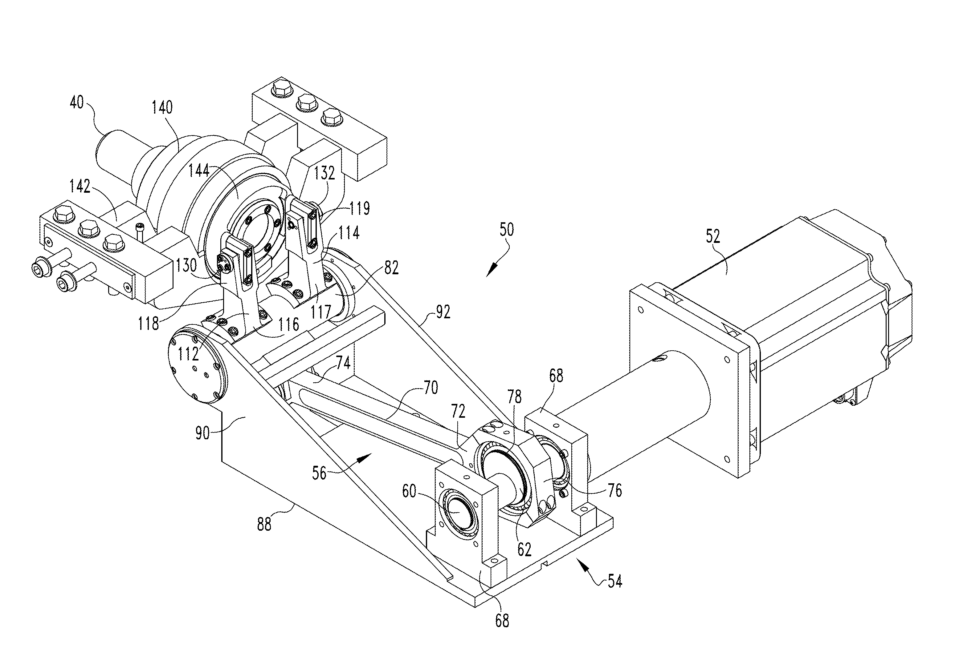
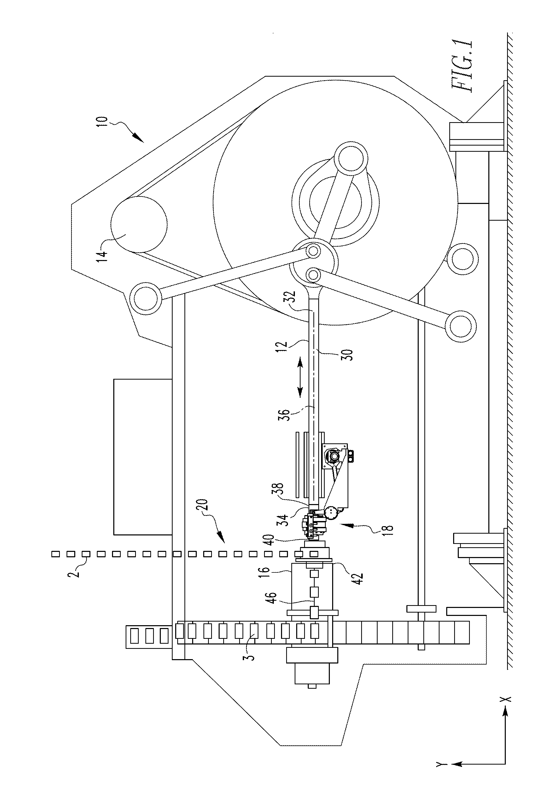
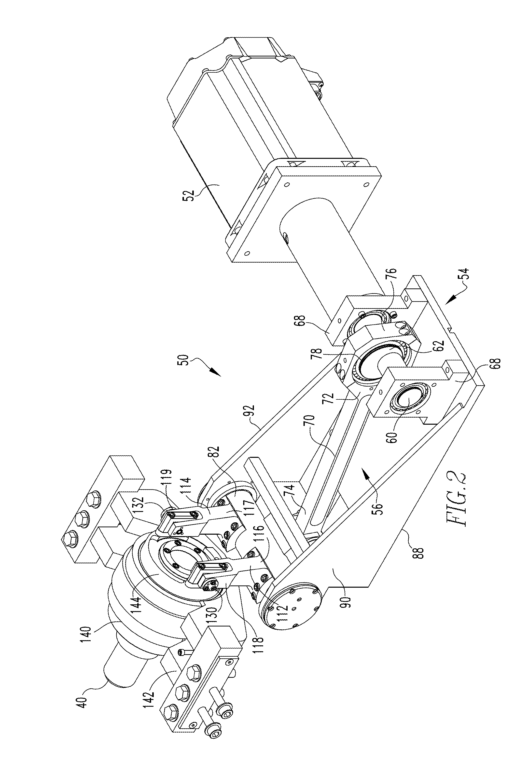
[0017]Directional phrases used herein, such as, for example, clockwise, counterclockwise, left, right, top, bottom, upwards, downwards and derivatives thereof, relate to the orientation of the elements shown in the drawings and are not limiting upon the claims unless expressly recited therein.

[0018]As used herein, the singular form of “a,”“an,” and “the” include plural references unless the context clearly dictates otherwise.

[0019]As used herein, the statement that two or more parts or components are “coupled” shall mean that the parts are joined or operate together either directly or indirectly, i.e., through one or more intermediate parts or components, so long as a link occurs. As used herein, “directly coupled” means that two elements are directly in contact with each other. As used herein, “fixedly coupled” or “fixed” means that two components are coupled so as to move as one while maintaining a constant orientation relative to each other. Further, an object resting on another ...


PUM

PropertyMeasurementUnit
Angular velocityaaaaaaaaaa

Abstract

An actuator for a redraw sleeve that operates independently of the ram drive mechanism is provided. The actuator utilizes an eccentric journal coupled to a drive shaft of a servomotor. The servomotor is structured to provide its output shaft with a variable rotation speed so as to accommodate the need for the redraw sleeve to be in selected locations at specific times. Further, the redraw sleeve includes a collapsing redraw cylinder to allow the redraw sleeve to dwell in a forward position.

Description

BACKGROUND OF THE INVENTION[0001]1. Field of the Invention[0002]The disclosed concept relates generally to a can bodymaker and, more specifically, to a can bodymaker having a redraw assembly actuated by an eccentric journal.[0003]2. Background Information[0004]Generally, an aluminum can begins as a disk of aluminum, also known as a “blank,” that is punched from a sheet or coil of aluminum. The blank is fed into a cupper. The cupper performs a blank and draw process to create a cup. That is, the blank is formed into a cup having a bottom and a depending sidewall. The cup is fed into one of several bodymakers, which perform a redraw and ironing operation. More specifically, the cup is disposed in a can forming machine at the mouth of a die pack having substantially circular openings therein. The cup is held in place by a redraw sleeve, which is part of the redraw assembly. The redraw sleeve is a hollow tubular construct that is disposed inside the cup and biases the cup against the di...

Claims


Application Information

Patent Timeline
IPC IPC(8): B21D22/28B21D51/26
CPCB21D51/26B21D22/28B30B1/06B30B1/268
Inventor HAULSEE, DONALD RAY
Owner STOLLE MACHINERY
Why Eureka
Try Eureka