
Thermal treatment vacuum furnace material transferring device

A technology of transfer device and vacuum furnace, applied in heat treatment equipment, quenching device, furnace, etc., can solve the problems that materials can not withstand friction on it, movement speed limitation, poor adaptability to heavy loads, etc., to achieve reliable work and avoid material friction , the effect of low failure rate

Active Publication Date: 2009-06-03
JIANGSU FENGDONG THERMAL TECH CO LTD
View PDF4 Cites 1 Cited by
  • Summary
  • Abstract
  • Description
  • Claims
  • Application Information

AI Technical Summary

Problems solved by technology

[0003] The purpose of the present invention is to provide a heat treatment vacuum furnace material transfer device to solve the problem in the prior art that when the temperature in the furnace is as high as 900 ° C, the material cannot withstand friction on it, and the movement speed is limited; and the four-connected The furnace body of the rod rolling transmission device has a large volume, large movement resistance, many mechanical failures, and poor adaptability to heavy loads.

Method used


Image

  • Thermal treatment vacuum furnace material transferring device
  • Thermal treatment vacuum furnace material transferring device
  • Thermal treatment vacuum furnace material transferring device

Examples


Embodiment Construction

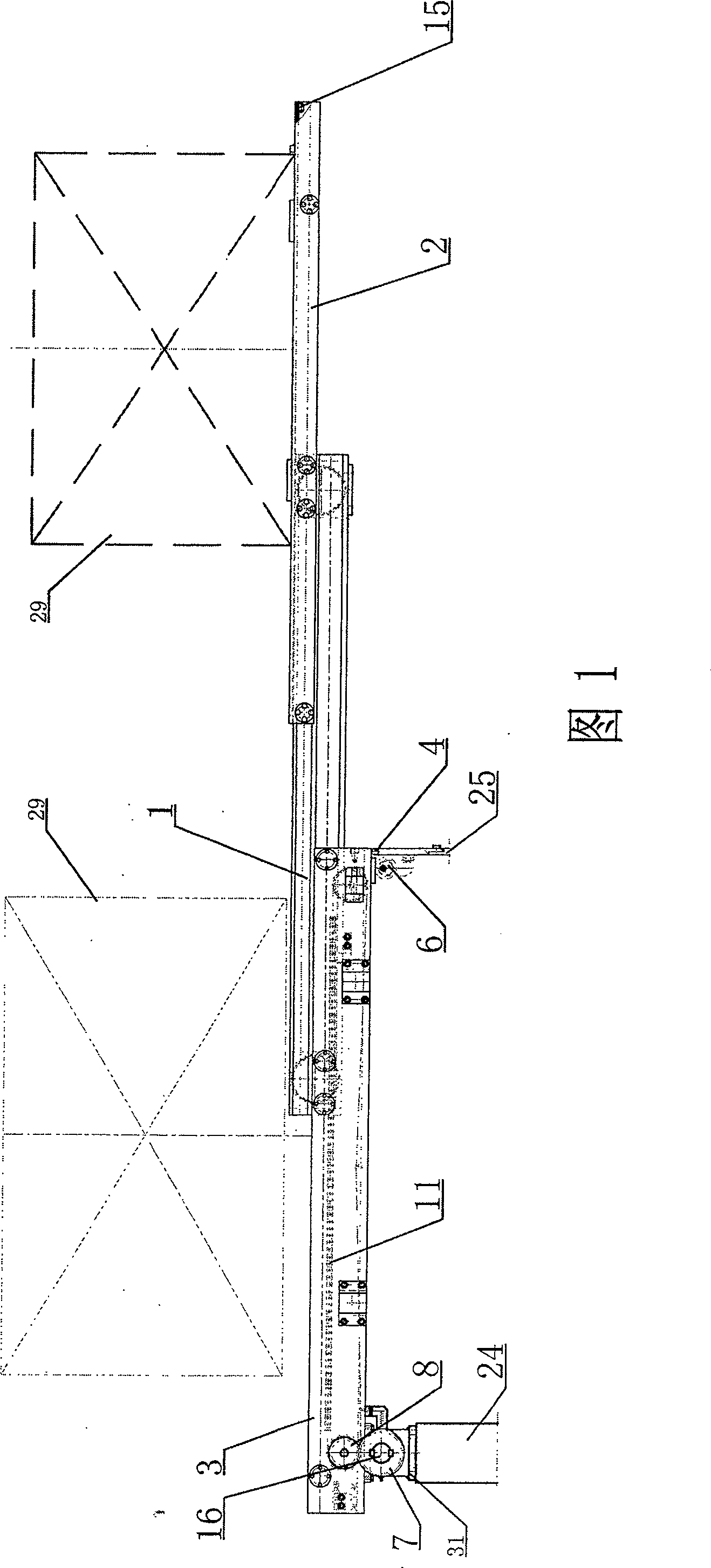
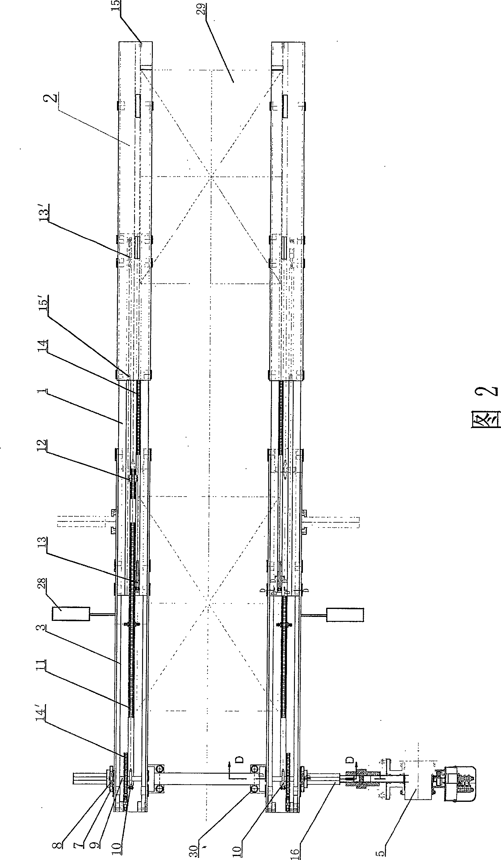
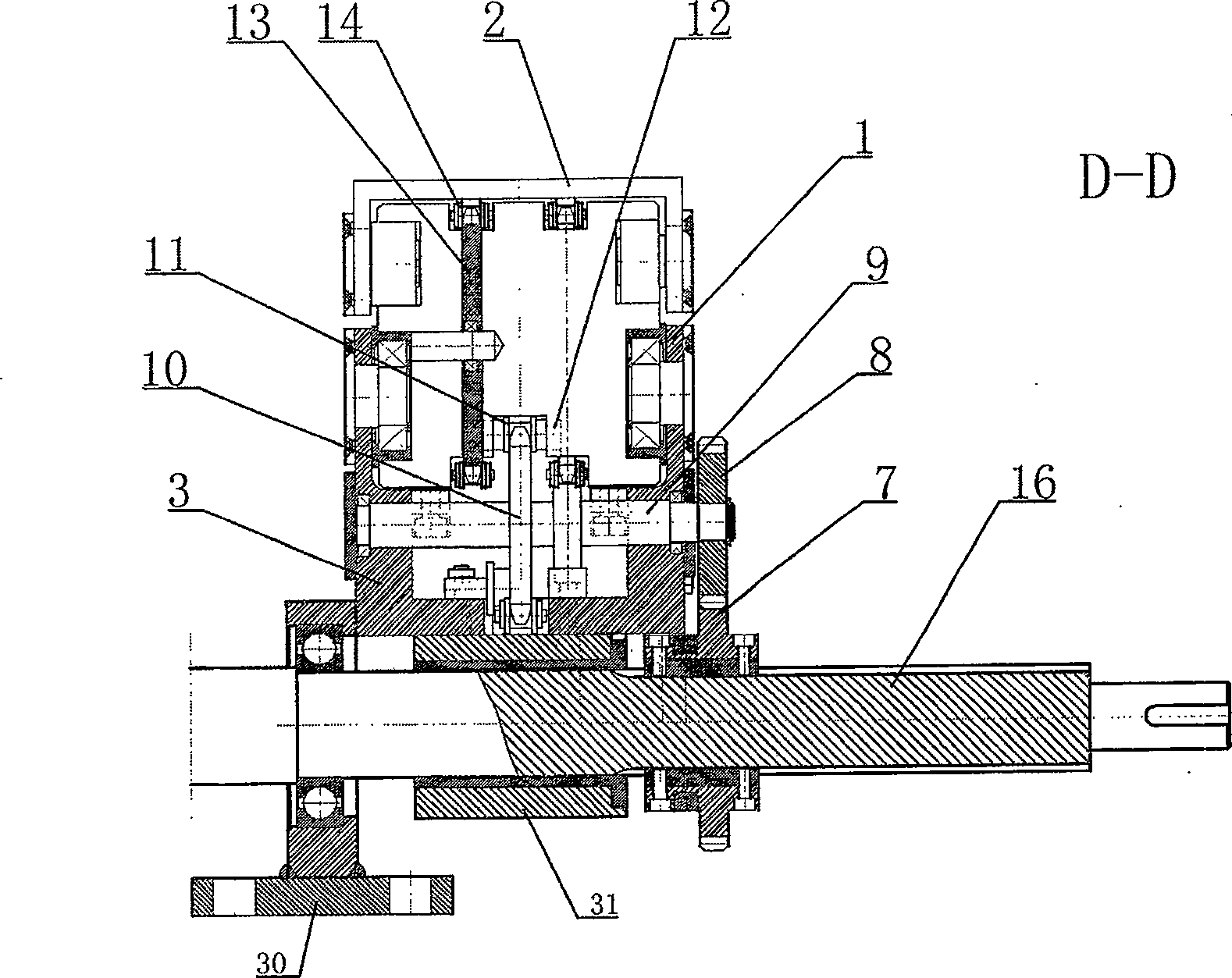
[0021] 1 to 7A, 7B and 7C, this embodiment of the present invention includes a ram 1, a ram seat 3, a slide plate 2 and a driving device, the ram 1 is slidably connected to the upper side of the ram seat 3, and the slide plate 2 is slidably connected to the upper side of the ram seat 3. On the upper side of the ram 1, a ram seat sprocket 10 is respectively installed at the two ends in the described ram seat 3, wherein one of the ram seat sprockets 10 is connected with the driving device through a transmission shaft 9; A ram drive chain 11 is installed between the two ram seat sprockets 10, and the ram drive chain 11 is connected with the ram 1 through a wedge 12. The ram seat sprocket 10, the ram driving chain 11 and the wedge 12 form the driving mechanism of the ram 1.

[0022] Front and rear ram sprockets 13' and 13 are installed at the front and rear ends of the ram 1 respectively, and a front and rear ram sprocket 13 are wound around the front of the front ram sprocket 13'...


PUM


Abstract

The invention is a heat treatment vacuum furnace material transferring device consisting of a ram, a ram seat, a sliding plate and a driving device. The ram is sliding connected to the upside of the ram seat, the sliding plate is sliding connected to the upside of the ram, the ram seat is equipped with a ram driving mechanism inside, one end of the ram driving mechanism is transmission jointed to the driving device by a transmission shaft, while the other end is jointed to the ram; each of two ends of the ram is equipped with a ram chain wheel, a sliding plate driving chain is equipped between the two ram chain wheels, the upper end of the sliding plate driving chain is connected to the sliding plate, the lower end of the sliding plate driving chain is connected to the ram seat; the ram seat is equipped on the support. The invention has several advantages, including simple structure, material friction avoidance, enough rigidity, small volume, motion flexibility, stability, reliable operation and low fault rate.

Description

technical field [0001] The invention relates to a heat treatment vacuum furnace material transfer device, which is a workpiece conveying device used in vacuum heat treatment equipment, capable of reciprocating workpieces with a load weight exceeding 600kg under high temperature (up to about 930°C) and fully enclosed negative conditions Translational movement, so as to realize the transfer of workpieces (materials). Background technique [0002] At present, the push-pull conveying method used abroad for heavy-duty materials has great limitations. When the temperature in the furnace is as high as 900 ° C, no matter how good the material is, it cannot withstand the friction on it, and the movement speed is limited. There are certain restrictions; the main domestic transmission mode is the four-link rolling transmission mode. This transmission device also has great limitations, such as large furnace body, large movement resistance, many mechanical failures, and poor adaptability...

Claims


Application Information

Patent Timeline
Patent Type & Authority Patents(China)
IPC IPC(8): C21D1/62F27D3/00
Inventor 向建华
Owner JIANGSU FENGDONG THERMAL TECH CO LTD
Learn More