Ring mill apparatus and method

a ring mill and apparatus technology, applied in the field of metal rolling, can solve the problems of inconvenient operation, large size and cost of motors, gearboxes, alignment coupling structures, and inability to meet the needs of production and repair, and achieve the effect of reducing vibration and/or oscillation of rings

Active Publication Date: 2009-05-07
FIRTH RIXSON
View PDF33 Cites 2 Cited by
  • Summary
  • Abstract
  • Description
  • Claims
  • Application Information

AI Technical Summary

Benefits of technology

[0004]Some embodiments of the invention provide a ring mill apparatus and method that utilize at least one direct drive motor to drive a roller in contact with the ring. The direct drive motor can include for example a hydraulic motor, a brushless DC motor (with a permanent magnet design with electronic switching) or a superconductor motor. The motor may be a radial piston hydraulic motor in some embodiments. Also, some embodiments more particularly use two opposed hydraulic or other direct drive motors. Some embodiments use the two opposed hydraulic or other direct drive motors to drive an upper king roller, which contacts the outside of the ring, and also use a lower mandrel roller, which contacts the inside of the ring. The lower mandrel roller in some cases may be laterally inserted inside the ring or retracted therefrom, and when inserted in a rolling position, is urged upwards against the ring by a ram driven carriage. In some examples, two hydraulic or other direct drive motors are provided in-line with, and directly connected to, the king roller. Also in some examples, an outer side of each hydraulic or other direct drive motor is restrained by a respective torque arm. Also in some embodiments, a pair of angled stabilizing swing arms urge respective support rollers on the outside of the ring which may in some cases reduce vibration and / or oscillation of the ring. The method in some embodiments includes using a hydraulic or other direct drive motor to rotate a roller in contact with a ring to expand the ring.

Problems solved by technology

However, the electric motor drives for the roller typically require gear reduction gearboxes and alignment couplings.
In certain cases, such as for example in the case of very large installations to make very large parts using high force, the complexity, size and cost of the motor, gearbox, and alignment coupling structures can be undesirably expensive, complex, large, and expensive to produce and repair.
Also, in some cases the original part to be rolled is imperfectly round, and so the rolling process transmits vibrations through the rollers back through the coupling and gearbox.
The couplings and gearboxes thus must be selected or made to accommodate this transmitted vibration, which leads to further cost and complexity of these parts.

Method used


Image

  • Ring mill apparatus and method
  • Ring mill apparatus and method
  • Ring mill apparatus and method

Examples


Embodiment Construction

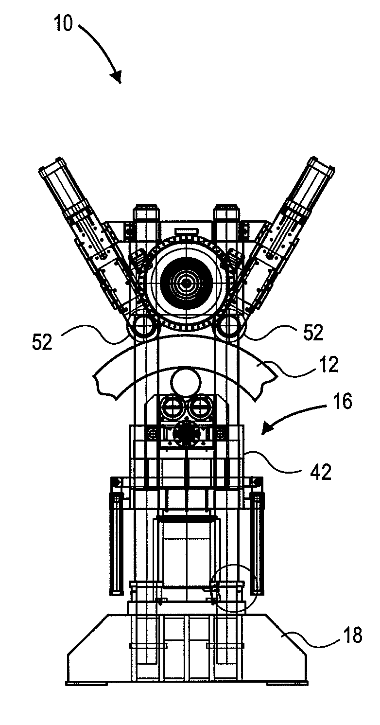
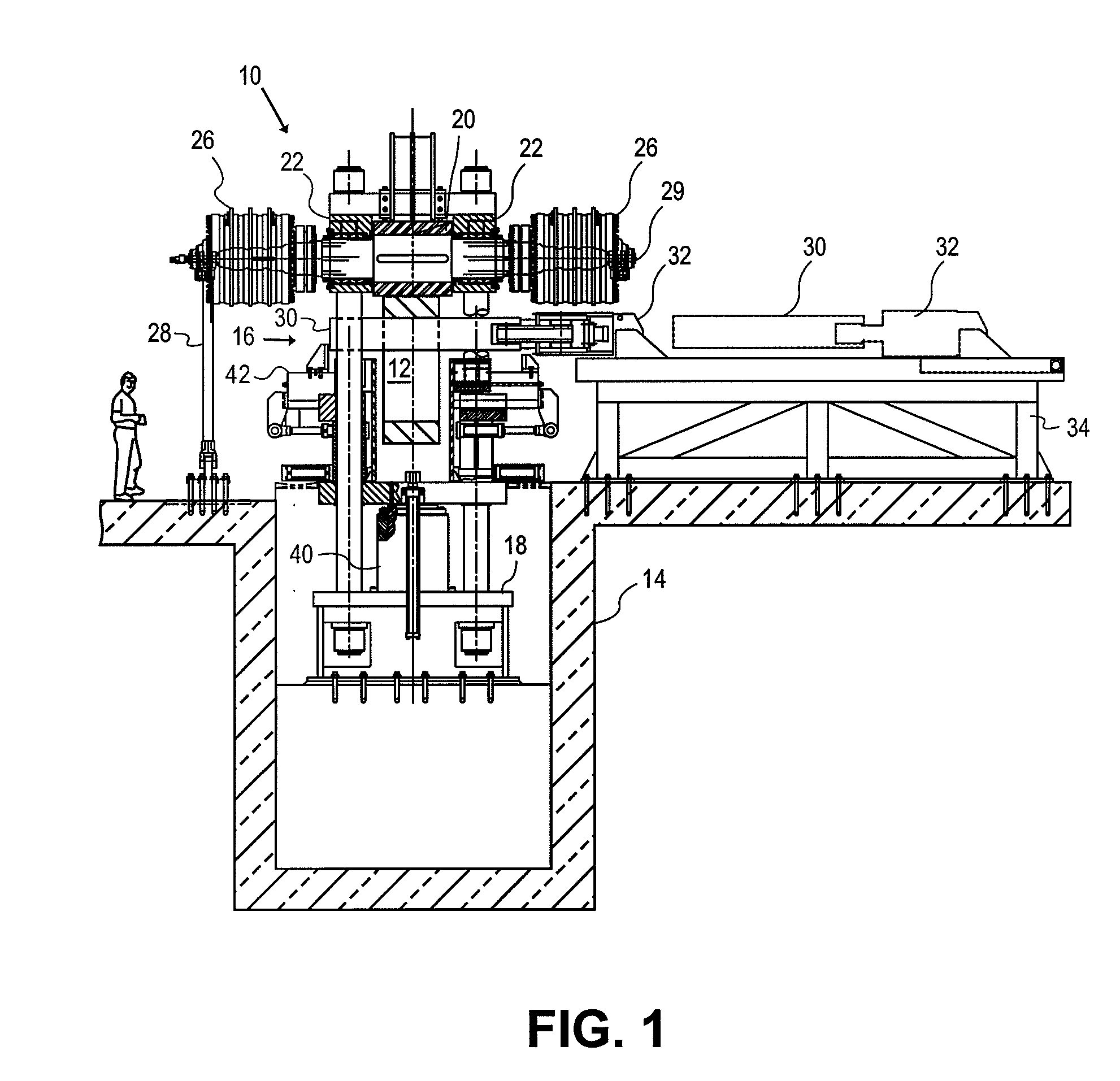
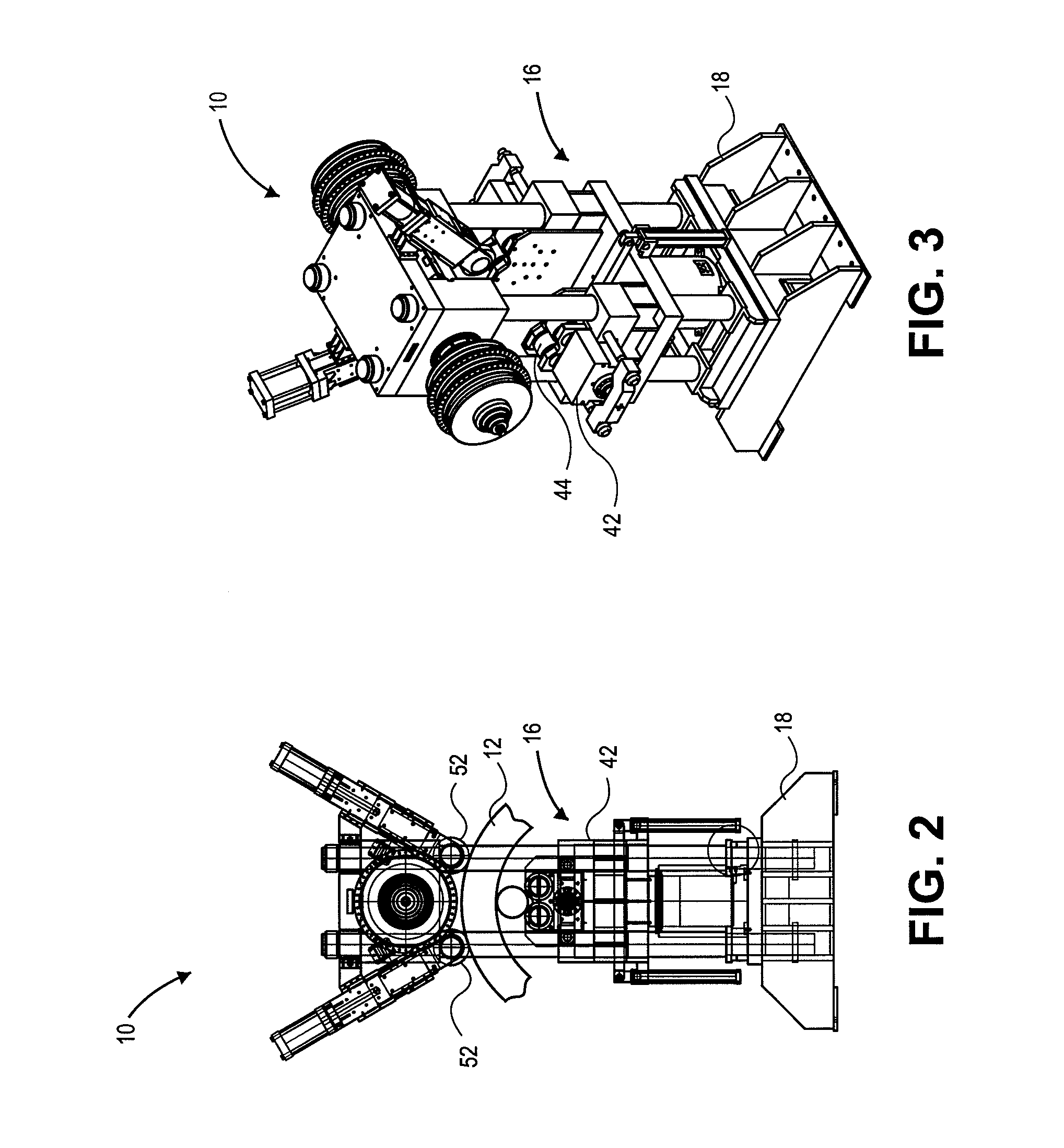
[0015]Some embodiments of the invention provide ring mill apparatus and method that utilize at least one direct drive motor to drive a roller. The direct drive motor can include for example a hydraulic motor, a brushless DC motor with a permanent magnet design with electronic switching, or a superconducting motor. Some embodiments more particularly use two opposed hydraulic motors. Some embodiments use the two opposed hydraulic motors to drive an upper king roller, which contacts the outside of the ring, and also use a lower mandrel roller, which contacts the inside of the ring. The lower mandrel roller in some cases may be laterally inserted inside the ring or retracted therefrom, and when inserted in a rolling position, is urged upwards against the ring by a ram driven carriage. In some examples, two hydraulic or other direct drive motors are provided in-line with the king roller. Also in some examples, an outer side of each hydraulic or other direct drive motor is restrained from...


PUM

PropertyMeasurementUnit
forceaaaaaaaaaa
torqueaaaaaaaaaa
diametersaaaaaaaaaa

Abstract

A ring mill apparatus and method utilizes at least one hydraulic or other direct drive motor to drive a roller in contact with a ring that is to be expanded by the ring mill. The motor may be two opposed radial piston hydraulic motors, to drive an upper king roller, which contacts the outside of the ring, which is inserted between the upper king roller and a lower mandrel roller, which contacts the inside of the ring. The lower mandrel roller is urged upwards against the ring by a ram driven carriage. Two hydraulic or other direct drive motors can be provided in-line with, and directly connected to, the king roller.

Description

FIELD OF THE INVENTION[0001]The invention relates to the field of metal rolling, and more particularly to devices and methods for forming a ring from a metal or alloy by vertically rolling the ring between rollersBACKGROUND OF THE INVENTION[0002]In many industries it is often desirable to form a large ring from various metal or alloy materials. Typically, in some examples, an initial hollow cylindrical ring is first manufactured, for example by forging and / or machining. In the case of some applications for the final ring, such as for example aerospace parts, the desired final rings may have large diameters and / or may be made of very high temperature alloys or superalloys. The initial hollow ring is then expanded to have a larger inner and outer diameter. One way of expanding a ring is by so-called vertical rolling, in which the ring is inserted so it is pinched with its thickness between two driven rollers. One of the rollers is driven and a compressive force is applied between the ...

Claims


Application Information

Patent Timeline
Patent Type & Authority Applications(United States)
IPC IPC(8): B21D15/04B21B31/07
CPCB21H1/06
Inventor HEBERT, DAVID
Owner FIRTH RIXSON
Why Eureka
Try Eureka