Dual measurement liquid level transducer

a liquid level transducer and dual-measurement technology, which is applied in the direction of liquid/fluent solid measurement, instruments, machines/engines, etc., can solve the problems of inability to determine the liquid level in the tank, unfavorable liquid level measurement, and high cos

Active Publication Date: 2015-03-12
ROCHESTER SENSORS LLC
View PDF1 Cites 20 Cited by
  • Summary
  • Abstract
  • Description
  • Claims
  • Application Information

AI Technical Summary

Benefits of technology

[0009]In accordance with one aspect of the invention, a transducer for determining the level of liquid within a container and includes a mounting head adapted for connection to the container and a sensor assembly adapted to extend into the container from the mounting head. The sensor has a sensor tube extending downwardly from the mounting head, a gauging rod assembly having an elongate rod positioned in the sensor tube for selective movement out of the tank for visually determining the liquid level, a first magnet connected to the gauging rod assembly, a float surrounding the sensor tube for sliding therealong in response to a change in liquid level, a second magnet connected to the float for selective coupling to the first magnet so that the gauging rod assembly and the float are selectively coupled together and a first sensor board extending along a length of the gauging rod assembly and being responsive to movement of the float for electronically determining the liquid level without the need to magnetically couple the gauging rod assembly to the float.

Problems solved by technology

Although such systems are adequate for their intended purpose, they are quite unwieldy, relatively expensive, and require the user to gain access to the top of the tank before a measurement can be taken, which can be both time consuming and dangerous.
Moreover, with these types of systems, it is not possible to determine the level of liquid in the tank from a remote location and / or when the tank is in transit.
Unfortunately, the coolant can leak into the area that holds the magnet, thereby destroying the magnet and causing expensive replacement in terms of both components and time, and possibly resulting in less accurate readings, or no reading at all depending on the level of damage to the magnet.
In addition, due to the relatively weak magnetic coupling forces between the float and gauging rod of the prior art, the capacity to obtain consistent readings is diminished, hysteresis is relatively high, and more especially when coolant or other fluids enter the magnetic coupler of the gauging rod thereby changing its weight and the coupling height with the float.
Also, prior art gauging rods are prone to frictional wear and eventual failure as they slide up and down inside the guide tube in response to changes in liquid level and / or a user pulling the gauging rod upwardly to couple with the float or remove the gauging rod from the tank, and pushing the gauging rod downwardly to its seated position.
Since a relatively large gap exists between the prior art magnetic coupler and the guide tube, the gauging rod may not couple efficiently with the float since it may be oriented at an angle other than coaxial with the guide tube.
Accordingly, both the accuracy and the coupling forces may be compromised.

Method used


Image

  • Dual measurement liquid level transducer
  • Dual measurement liquid level transducer
  • Dual measurement liquid level transducer

Examples


Embodiment Construction

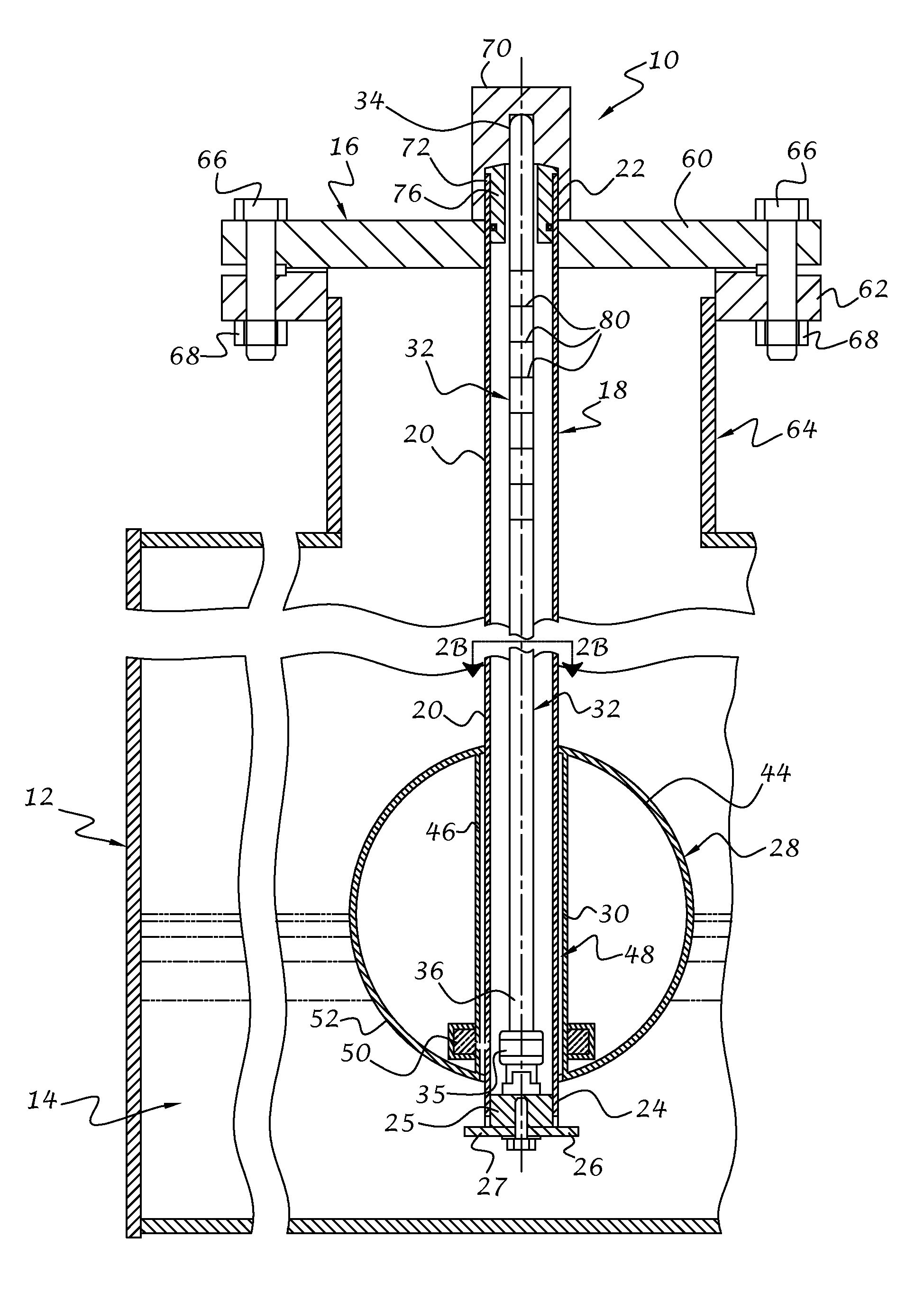
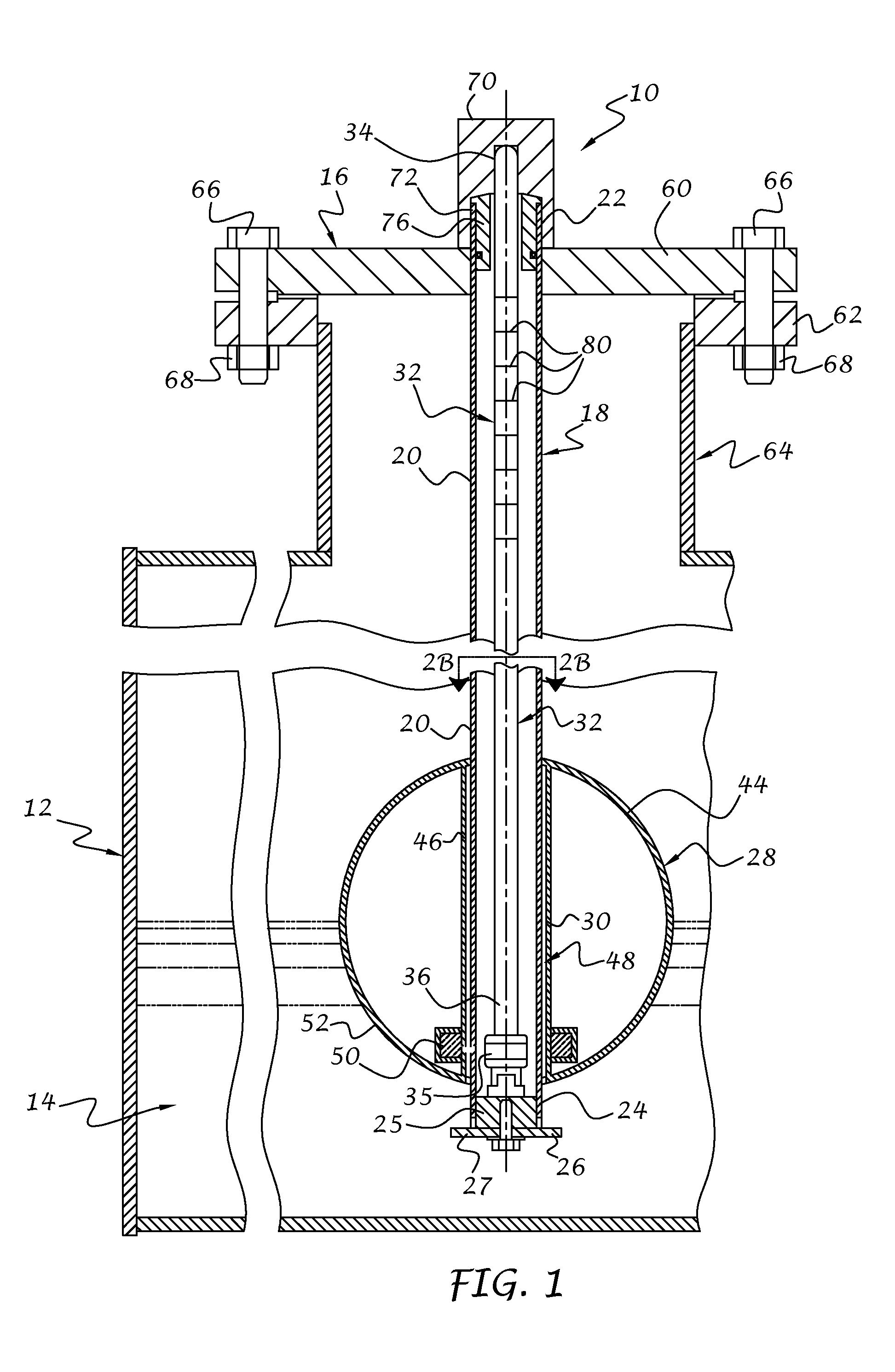
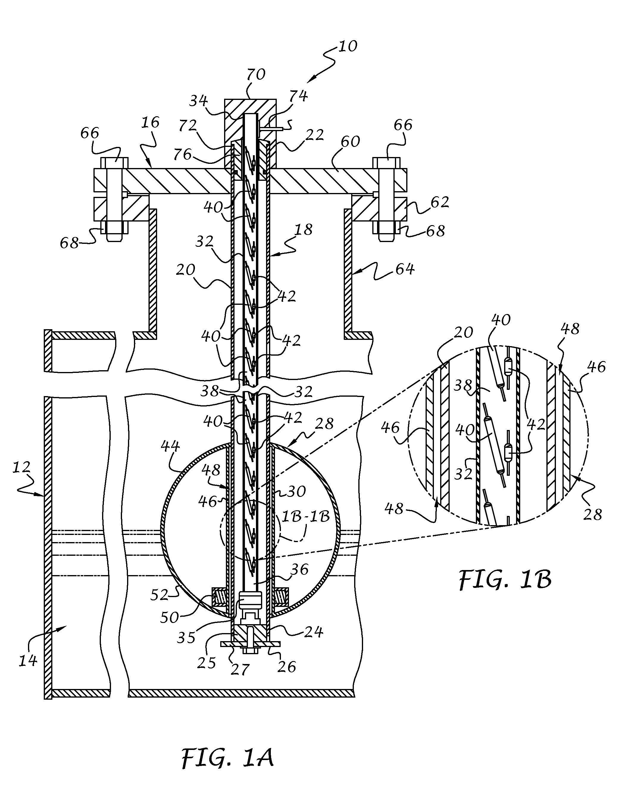
[0024]Referring now to the drawings, and to FIGS. 1, 1A and 1B in particular, a liquid level transducer assembly 10 in accordance with an exemplary embodiment of the present invention is illustrated. The liquid level transducer assembly 10 preferably extends into a tank 12, which may be associated with railroad tanker cars, semi-trailer tankers, large stationary storage tanks, or any other container for holding and / or transporting a liquid 14 where it is desirous to determine the level of liquid within the tank and / or to determine when the tank has been adequately filled and / or emptied.

[0025]The transducer assembly 10 preferably includes a mounting head assembly 16 and an elongate sensing probe assembly 18 extending into the mounting head assembly 16 and oriented for extending downwardly into the tank.

[0026]The sensing probe assembly 18 preferably senses liquid level in a linear direction and, in accordance with one preferred embodiment of the invention, includes an outer sensor gui...


PUM


Abstract

A liquid level transducer for a tank, such as a railroad tank car or the like, includes a mounting head connected to the tank and a sensor assembly extending into the tank from the mounting head. The sensor assembly includes a sensor tube located in the tank and a gauging rod assembly positioned in the sensor tube. The gauging rod assembly can be pulled out of the tank until it magnetically couples with a magnetic float that surrounds the sensor tube. The float moves in response to a change in liquid level and the magnetic coupling provides the user with a visual indication of the liquid level. A sensor board extends along a length of the gauging rod assembly and is responsive to movement of the float for electronically determining the liquid level without the need to magnetically couple the gauging rod assembly to the float.

Description

CROSS-REFERENCE TO RELATED APPLICATIONS[0001]This application claims the benefit of U.S. Provisional Application No. 61 / 876,078 filed on Sep. 10, 2014, the disclosure of which is hereby incorporated by reference.BACKGROUND OF THE INVENTION[0002]This invention relates to liquid level transducers, and more particularly to a liquid level transducer having a magnetic float that moves in response to a change in liquid level.[0003]U.S. Pat. No. 3,815,416 to Dean et al. discloses a prior art apparatus for indicating the level of liquid in a tank car. The apparatus includes a float encircling a guide tube extending down into the tank. The float is magnetically coupled to a gauging rod which bears indicia representing the level of liquid in the tank. The gauging rod is normally retained inside the guide tube via an upper cover removably secured to the tank opening. When it is desirous to check the liquid level within the tank, the cover is removed and the gauging rod is manually raised until...

Claims


Application Information

Patent Timeline
Patent Type & Authority Applications(United States)
IPC IPC(8): G01F23/62G01F23/28
CPCG01F23/28G01F23/62G01F23/74G01F23/76G01F23/04G01F23/72G01F23/66G01F23/68G01F23/683
Inventor ROSS, JR., HERBERT G.FARMANYAN, GAGIKTAYLOR, CARL ALAN
Owner ROCHESTER SENSORS LLC
Why Eureka
Try Eureka