
Thermal management system and method of assembling the same

a technology of management system and heat management system, which is applied in the direction of energy-efficient board measures, lighting and heating apparatus, and modification by conduction heat transfer, etc., can solve the problems of ineffective cooling of electronics and inefficient use of heat generated by electronics

Inactive Publication Date: 2015-03-12
GENERAL ELECTRIC CO +1
View PDF29 Cites 45 Cited by
  • Summary
  • Abstract
  • Description
  • Claims
  • Application Information

AI Technical Summary

Benefits of technology

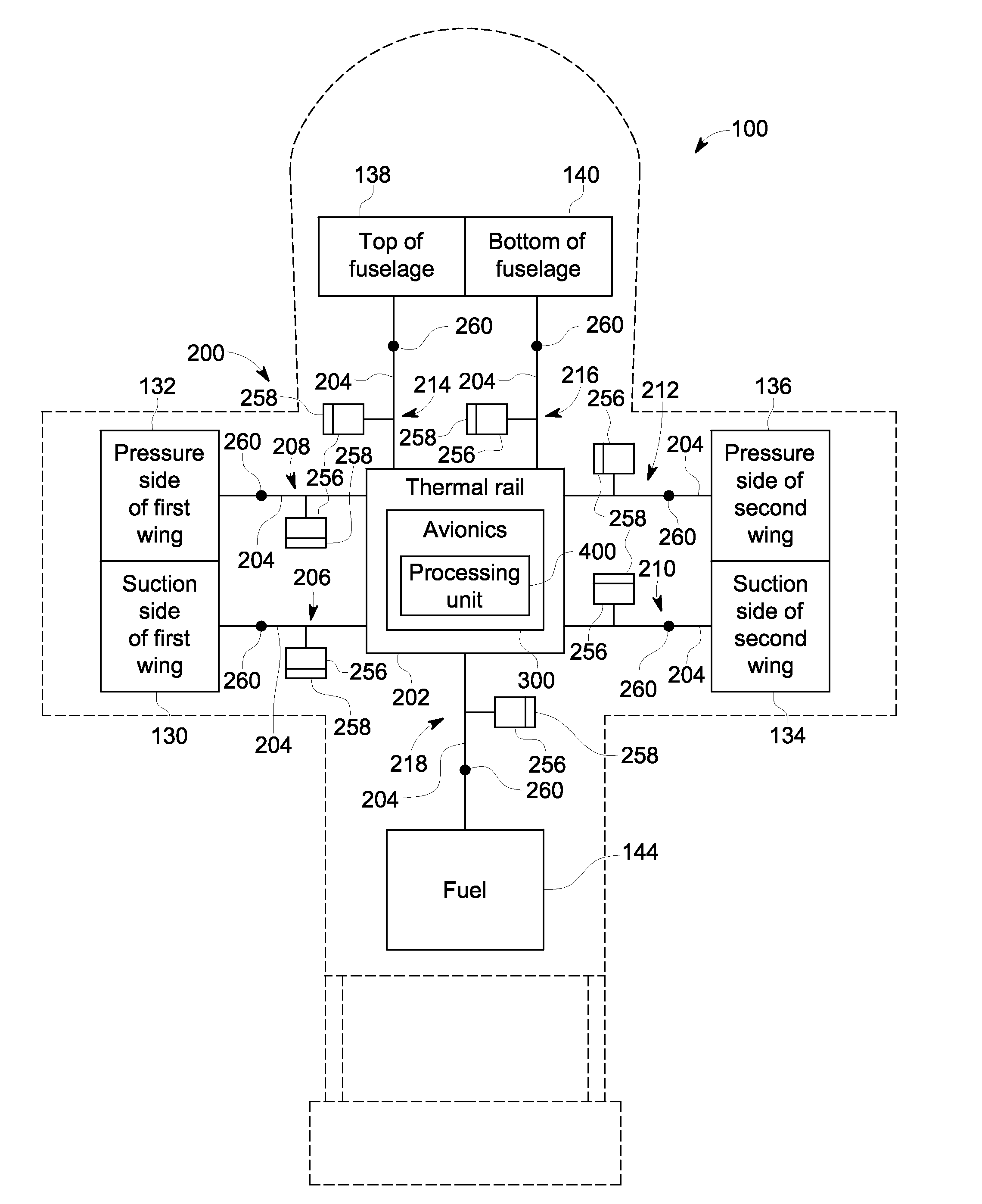
The patent text describes a system for cooling a heat source on an aircraft using heat pipes. The system has two networks of heat pipes that are in conductive heat transfer with the heat source and the skin of the aircraft. The first network of heat pipes is designed to heat the first segment of the skin while the second network of heat pipes is designed to heat the second segment of the skin. The system also includes a processing unit that can selectively deactivate either the first or second network of heat pipes. The technical effect of this system is to provide efficient cooling for the heat source on an aircraft, minimizing the impact on the overall aircraft performance.

Problems solved by technology

However, in some circumstances, these known cooling systems are ineffective at cooling the electronics and make inefficient use of the heat generated by the electronics.

Method used


Image

  • Thermal management system and method of assembling the same
  • Thermal management system and method of assembling the same
  • Thermal management system and method of assembling the same

Examples


Embodiment Construction

[0014]In the following specification and the claims, reference will be made to a number of terms, which shall be defined to have the following meanings.

[0015]The singular forms “a”, “an”, and “the” include plural references unless the context clearly dictates otherwise.

[0016]“Optional” or “optionally” means that the subsequently described event or circumstance may or may not occur, and that the description includes instances where the event occurs and instances where it does not.

[0017]Approximating language, as used herein throughout the specification and claims, may be applied to modify any quantitative representation that could permissibly vary without resulting in a change in the basic function to which it is related. Accordingly, a value modified by a term or terms, such as “about” and “substantially”, are not to be limited to the precise value specified. In at least some instances, the approximating language may correspond to the precision of an instrument for measuring the val...


PUM


Abstract

A thermal management system for cooling a heat source onboard an aircraft that has a frame and a skin coupled to the frame such that the skin has a first segment and a second segment includes a first network of heat pipes coupled in conductive heat transfer with the heat source and the first segment of skin. The first network of heat pipes is configured to heat the first segment of skin using heat from the heat source. The thermal management system further includes a second network of heat pipes coupled in conductive heat transfer with the heat source and the second segment of skin. The second network of heat pipes is configured to heat the second segment of skin using heat from the heat source. The thermal management system is configured to selectively deactivate the first network of heat pipes and the second network of heat pipes.

Description

BACKGROUND[0001]The subject matter described herein relates generally to thermal management systems and, more particularly, to a thermal management system for cooling a heat source onboard an aircraft.[0002]Many aircraft utilize electronic systems that generate significant amounts of heat, and the heat should be dissipated from the electronic systems in order to keep the systems functioning properly. At least some known cooling systems for dissipating heat from the electronics on an aircraft include forced-air cooling systems (e.g., cooling systems that blow air over the electronics using ductwork) or forced-liquid cooling systems (e.g., cooling systems that channel liquid coolant through a cooling circuit using a pump). However, in some circumstances, these known cooling systems are ineffective at cooling the electronics and make inefficient use of the heat generated by the electronics.BRIEF DESCRIPTION[0003]In one aspect, a thermal management system for cooling a heat source onboa...

Claims


Application Information

Patent Timeline
Patent Type & Authority Applications(United States)
IPC IPC(8): H05K7/20
CPCH05K7/20854H05K2007/20527H05K7/2039B64D13/00B64D2013/0607F28F2210/02F28D15/0233F28D15/0266F28D2015/0216F28D15/0275F28D15/046Y02T50/50
Inventor DE BOCK, HENDRIK PIETER JACOBUSDUNSDON, JONATHAN MARKENGELHARDT, MICHEL
Owner GENERAL ELECTRIC CO
Learn More