
Hand held planer

a planer and hand-held technology, applied in the field of hand-held planers, can solve the problems of difficult and potentially hazardous termination of planing at the end of the workpiece, and inability to operate in confined spaces or near obstructions, and achieve the effect of facilitating the plunge planing

Inactive Publication Date: 2015-03-19
ACCESS TOOLING
View PDF6 Cites 3 Cited by
  • Summary
  • Abstract
  • Description
  • Claims
  • Application Information

AI Technical Summary

Benefits of technology

The patent describes a planer that has an adjustable base that can be moved between two different configurations. One configuration makes the planer longer, while the other configuration makes it shorter. The size of the adjustable base in contact with the surface of the material being worked on is reduced or eliminated when in the shorter configuration. The planer also has a handle that can be moved between two positions, with one position preventing the base from being moved into the shorter configuration. The removable portion of the base can be the entire base, allowing for plunge planing. The technical effects of this invention include increased flexibility, improved performance, and easier use of the planer in different situations.

Problems solved by technology

Such wood planers are effective when operating in open, unobstructed spaces, but are ill suited for operating in confined spaces or near an obstruction because of the restrictions imposed by the length of the base plates, and where small amounts of wood stock may need to be shaved.
Initiating planing by plunging the planing tool straight into the work piece at some position a distance away from the conventional starting point is both difficult, since the trailing base plate is conventionally in line with the cutting arc of the planing tool, and unhelpful since this leaves a substantial amount of wood stock between the plunge point and the start of the work piece still to be removed by other means.
However, an absent or minimal trailing base plate makes termination of planing at the end of the work piece both difficult and potentially hazardous, since the trailing base plate performs an important role in stabilising the planer at the end of the planing process.
Where there is an obstruction close to the end of the work piece the position of the leading base plate limits the positioning of the cutting arc and thereby the termination of planing to a point before the end of the work piece.
However, an absent or minimal leading base plate makes initiation of planing both difficult and potentially hazardous, since the leading base plate performs an important role in stabilising the planer at the start of the planing process.
Further, since positioning of the leading base plate is the principal means by which the depth of cut can be controlled its complete removal is not practical.
This task is laborious, and time consuming, and bears the risk of handling damage.
Furthermore, for shaving wood stock from a bowed or misaligned framing stud or stud noggin located near an obstruction, use of a conventional wood planer may not be possible and instead a hammer and a chisel may be required.
Although a hammer and chisel may be used for this purpose, they are both laborious and time consuming, and require a high degree of skill.
It has been found by the present inventors that none of the prior art apparatus and methods provide an effective, stable and unhazardous means of shaving or planing small amounts of wood stock from a door, framing stud, stud noggin or other work piece as may be required for small adjustments in thickness in confined spaces or near an obstruction, whether the confinement or obstruction is located at the start or at the end of the work piece.

Method used


Image

  • Hand held planer
  • Hand held planer
  • Hand held planer

Examples


Embodiment Construction

[0044]An embodiment of the current invention will now be described.

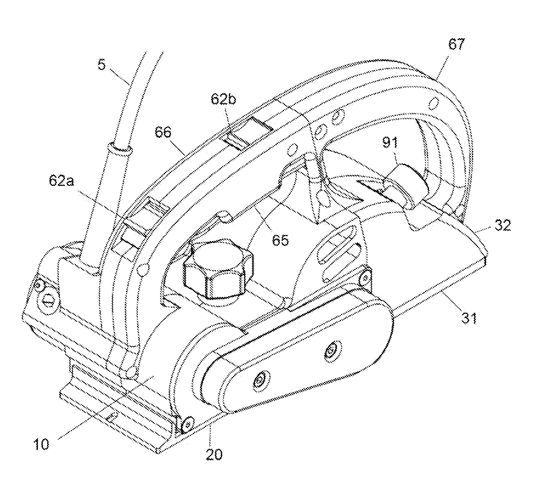
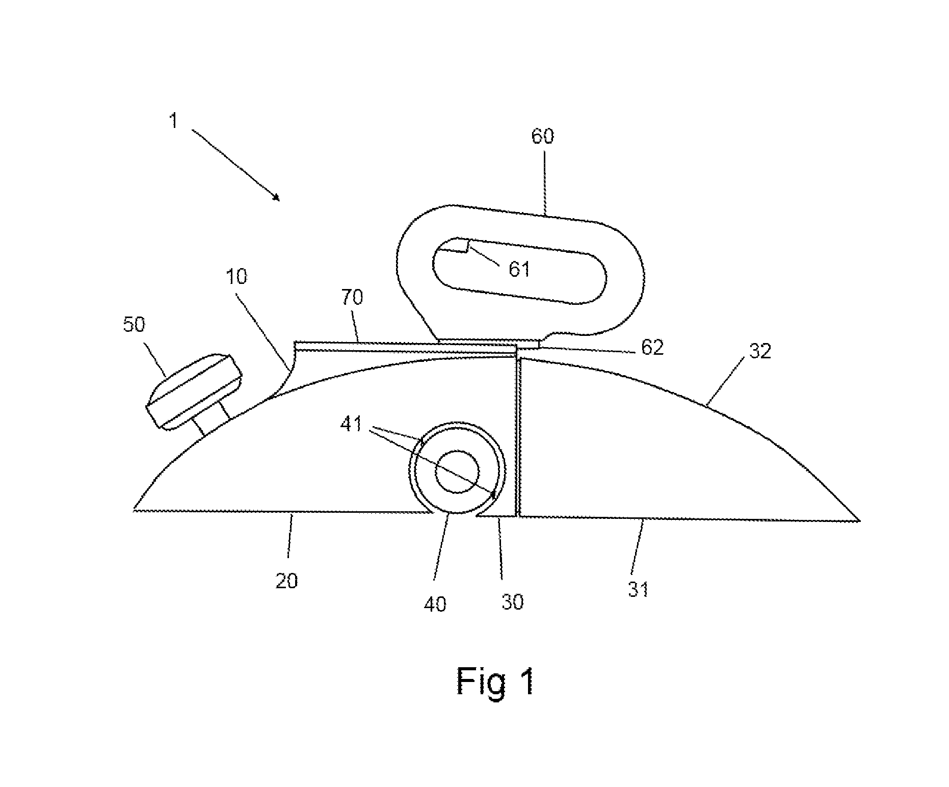
[0045]Referring first to FIG. 1, there is shown a planer 1 comprising a housing 10. Disposed within the housing 10 is a first base 20 and a cylindrical electrically powered planing tool 40 with tool tips or planer blades 41 for planing off a thickness of a work piece.

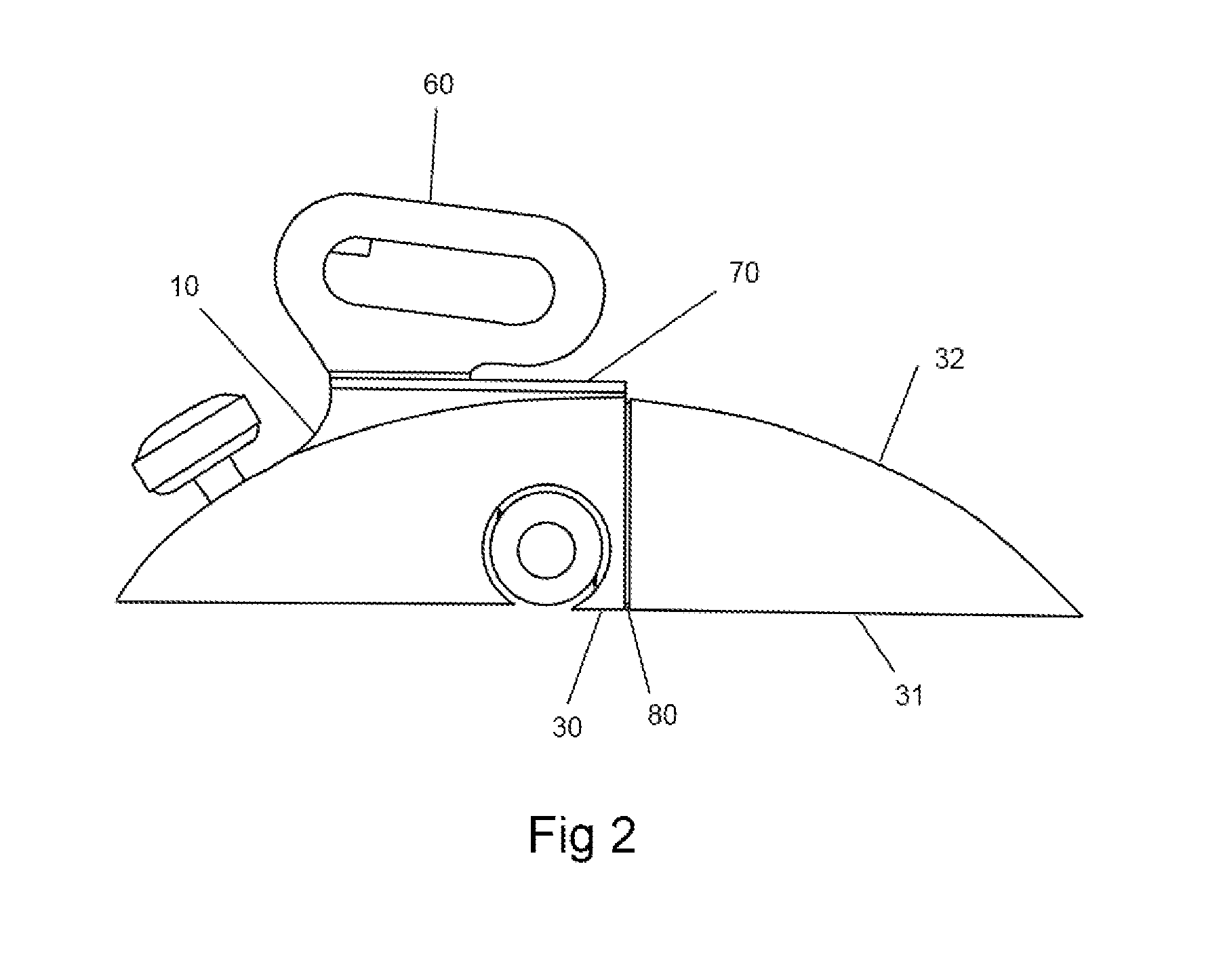
[0046]A second base in a trailing disposition to planing tool 40 is an adjustable base, being a composite of juxtaposed portions 30 and 31. Portion 31 provides the adjustment, being a removable portion forming part of a removable piece 32, the operation of which will be described later.

[0047]Planer 1 further comprises a knob 50 and handle 60 with trigger 61 to operate the planing tool 40. A user holds handle 60 in one hand and knob 50 in the other hand, and moves the planer along a work piece surface with first base 20 leading and second base 30,31 trailing, with first base 20 and second base 30, 31 guiding the planer along the work piece surface, and th...


PUM


Abstract

The invention provides a hand held planer (1) for planing a work piece surface comprising a planing tool (41) disposed between a first base (20) and a second base (30,31), the planer (1) being configurable so that it can be moved by hand along the work piece surface with the first base (20) leading and the first (20) and second (30,31) bases guiding the planer (1) along the work piece surface and the planing tool planing off a thickness of the work piece, whereinat least one (30,31) of the bases is an adjustable base such that at least a portion (31) thereof is removable or movable between a position that provides an operable lengthened configuration and a position that provides an operable shortened configuration such that a length of the adjustable base in guiding contact with the work piece surface is reduced or eliminated in the shortened configuration compared to the lengthened configuration.

Description

FIELD[0001]The present invention relates to improvements in hand held planers such as electric wood planers for shaving small amounts of wood stock from a door, frame or other work piece as may be required for small adjustments in thickness. More particularly, the present invention relates to a planer having a section or sections of its base that can be repositioned upon the planer or removed in their entirety.[0002]Although the background, objects and preferred embodiments of the invention will be hereinafter described with reference to a hand held, electrically powered, wood planer for shaving wood stock of, 15 to 80 mm breadth from a wooden structure that may be located in a confined space or near an obstruction in a room under renovation or construction, it is to be understood that the invention is not limited thereto but potentially has wider application.BACKGROUND[0003]Hand held, electrically powered, wood planers are well known in the art. Conventionally, such wood planers co...

Claims


Application Information

Patent Timeline
Patent Type & Authority Applications(United States)
IPC IPC(8): B27C1/10B27G17/02
CPCB27G17/02B27C1/10
Inventor ATLAGIC, PETERTANOUSIS, KIKI
Owner ACCESS TOOLING
Learn More