
Image forming apparatus, image forming method, and computer program product

Active Publication Date: 2015-03-19
RICOH KK
View PDF2 Cites 10 Cited by
  • Summary
  • Abstract
  • Description
  • Claims
  • Application Information

AI Technical Summary

Benefits of technology

The invention relates to an image forming apparatus that can produce different types of prints, such as clear toner, color toner, and special color toner. The apparatus includes an acquisition unit that collects output data, which includes at least one image and associated information. The apparatus has three output units, each responsible for producing different types of prints. The first output unit produces clear toner prints on the first recording medium, the second output unit produces color prints and special color prints on the first or second recording medium, and the third output unit produces clear toner prints on the second recording medium. The apparatus can automatically identify which type of print is needed and produce the appropriate type of print without requiring manual adjustments. The technical effect of the invention is to simplify the process of printing different types of images and to make it easier to produce special color prints.

Problems solved by technology

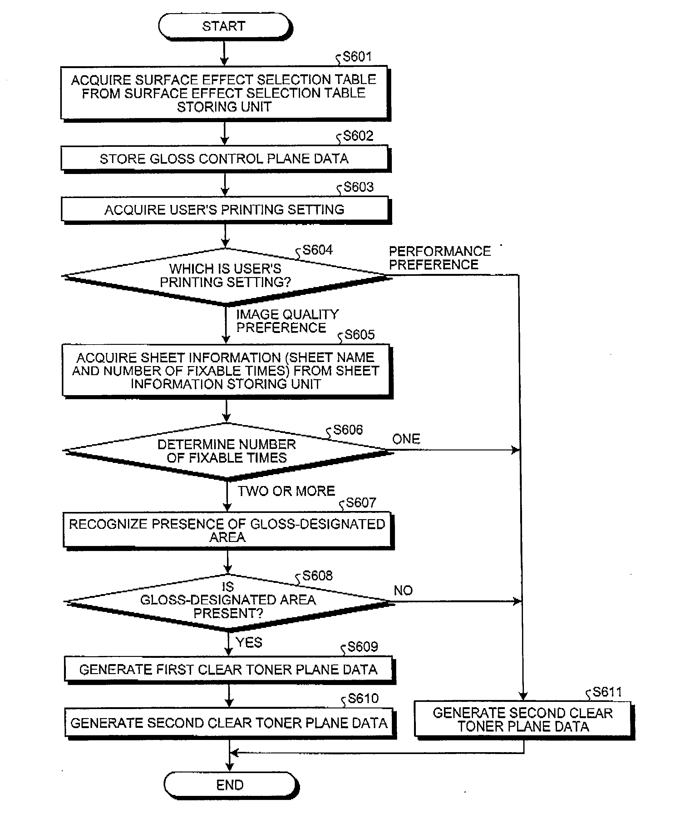
However, in the conventional technology, in order to perform two-pass printing using one image forming apparatus, also for a sheet for which printing of the first time is not necessary, printing is performed twice, and there is a problem in that a time corresponding to the printing for the sheet for which the printing of the first time is not necessary is wasted.

Method used


Image

  • Image forming apparatus, image forming method, and computer program product
  • Image forming apparatus, image forming method, and computer program product
  • Image forming apparatus, image forming method, and computer program product

Examples


first embodiment

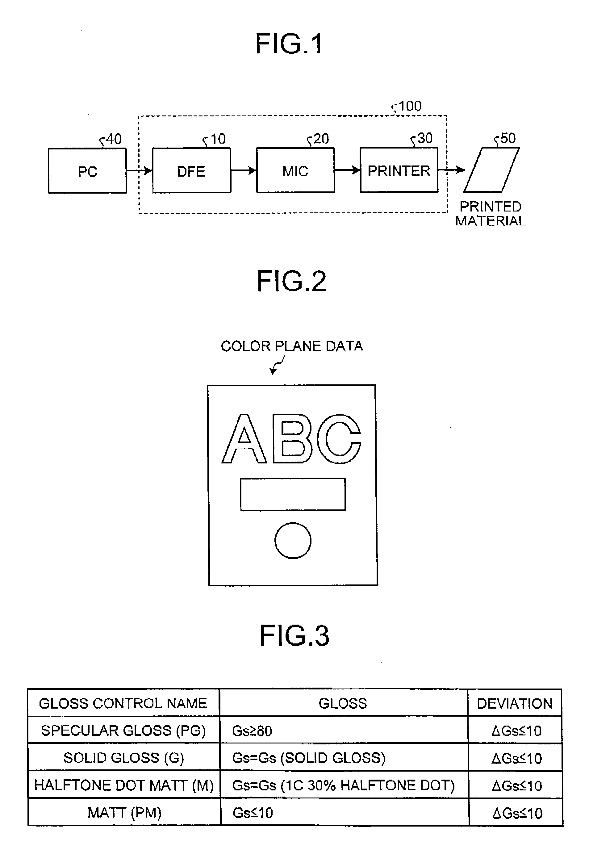
[0035]First, an example of the configuration of an image forming apparatus (image forming system) according to a first embodiment will be described with reference to FIG. 1. FIG. 1 is a block diagram that illustrates an example of the schematic configuration of an image forming apparatus 100 according to the first embodiment. As illustrated in FIG. 1, the image forming apparatus 100 is configured by connecting a control device (DFE: Digital Front End) 10, an interface controller (MIC: Mechanism I / F Controller) 20, and a printer (image forming unit) 30 together.

[0036]The DFE 10 communicates with the printer 30 through the MIC 20, thereby controlling the formation of an image in the printer 30. In addition, a personal computer (PC) 40 is connected (may be connected through a network) to the DEE 10. The PC 40 generates document data described in a language such as a page description language (PDL) using an application that is installed in advance and transmits the generated document da...

second embodiment

[0200]In the first embodiment, while the print data generating process is configured to be performed by the DFE 10, the present invention is not limited thereto.

[0201]Any one of the plurality of processes performed by one apparatus may be configured to be performed by one or more other apparatuses connected to the apparatus through a network.

[0202]As an example, in an image forming system according to a second embodiment, some of the functions of the DFE are mounted on a server apparatus on a network.

[0203]FIG. 19 is a diagram that illustrates an example of the configuration of the image forming system according to the second embodiment. As illustrated in FIG. 19, the image forming system according to the second embodiment includes: a PC 40; a DEE 3050; an MIC 20; a printer 30; and a server apparatus 3060 on a cloud.

[0204]In the second embodiment, the DFE 3050 and the server apparatus 3060 are interconnected through a network such as the Internet. In addition, in the second embodime...


PUM


Abstract

An acquisition unit acquires output data including first image data including first clear toner plane data and second image data including color plane data and second clear toner plane data. When the output data includes the first image data, a first output unit outputs first print data including first identification information representing an instruction to form an image on a first recording medium to which clear toner has not been applied to an image forming unit. When the output image includes the first image data and the second image data, a second output unit outputs second print data including second identification information representing an image formation instruction for a second recording medium to which the clear toner has been applied. When the output data does not include the first image data but includes the second image data, the second output unit outputs third print data including the first identification information.

Description

CROSS-REFERENCE TO RELATED APPLICATIONS[0001]The present application claims priority to and incorporates by reference the entire contents of Japanese Patent Application No. 2013-192417 filed in Japan on Sep. 17, 2013 and Japanese Patent Application No. 2014-166160 filed in Japan on Aug. 18, 2014.BACKGROUND OF THE INVENTION[0002]1. Field of the Invention[0003]The present invention relates to an image forming apparatus, an image forming method, and a computer program product.[0004]2. Description of the Related Art[0005]A technology for raising the glossiness of an image by printing toner of four colors including cyan, magenta, yellow, and black and clear toner on a sheet in an overlapping manner has been known. For example, there is a technology for completing image formation by performing printing for one sheet twice (hereinafter, referred to as a two-pass printing).[0006]In addition, in Japanese Patent Application Laid-open No. 2012-150361, a printing system has been disclosed in wh...

Claims


Application Information

Patent Timeline
IPC IPC(8): G03G15/01
CPCG03G15/01G03G15/50G03G15/6585G03G15/6579G03G2215/00447G03G2215/00751
Inventor KOGUSURI, YUJI
Owner RICOH KK
Learn More