Telescopic strut for an external fixator

a technology of fixator and telescopic strut, which is applied in the field of telescopic strut for an external fixator, can solve problems such as difficulty in adjustment, and achieve the effect of improving the ease of adjusting the length of the rod

Active Publication Date: 2015-03-19
STRYKER EURO OPERATIONS HLDG LLC
View PDF9 Cites 16 Cited by
  • Summary
  • Abstract
  • Description
  • Claims
  • Application Information

AI Technical Summary

Benefits of technology

[0006]However, these devices, which can be used to shorten or lengthen the telescopic struts, are difficult to adjust and it is one aspect of the invention to improve the ease of adjusting the length of the rod. Furthermore, a simple method of length adjustment and dynamization for each strut is desired.
[0007]Based on the prior art, it is therefore an aspect of the invention to provide a telescopic strut, which can be readily and quickly changed in its length.
[0009]In view of the above mentioned aspect it is furthermore another aspect of the invention to allow a quick switch between the two functions, i.e., to allow a quick first definition of the length of the telescopic element, and additionally, to switch for a fine adjustment of said length.
[0010]It is yet another aspect to provide a variable dynamization function to the strut which allows micro-motion at a fracture / fusion site to promote healing.
[0013]The grooves in the rod may be formed by a helical thread extending along the axial extent thereof so that rotation of the rod with the balls engaged lengthens the strut.

Problems solved by technology

However, these devices, which can be used to shorten or lengthen the telescopic struts, are difficult to adjust and it is one aspect of the invention to improve the ease of adjusting the length of the rod.

Method used


Image

  • Telescopic strut for an external fixator
  • Telescopic strut for an external fixator
  • Telescopic strut for an external fixator

Examples


Embodiment Construction

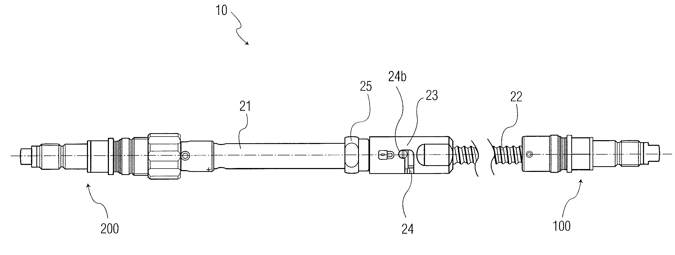
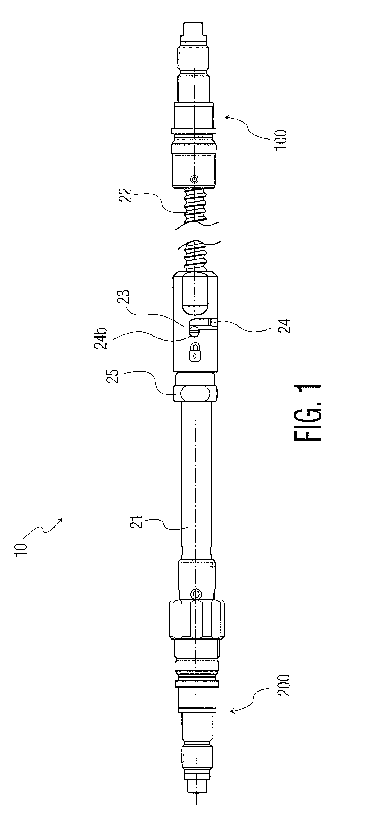
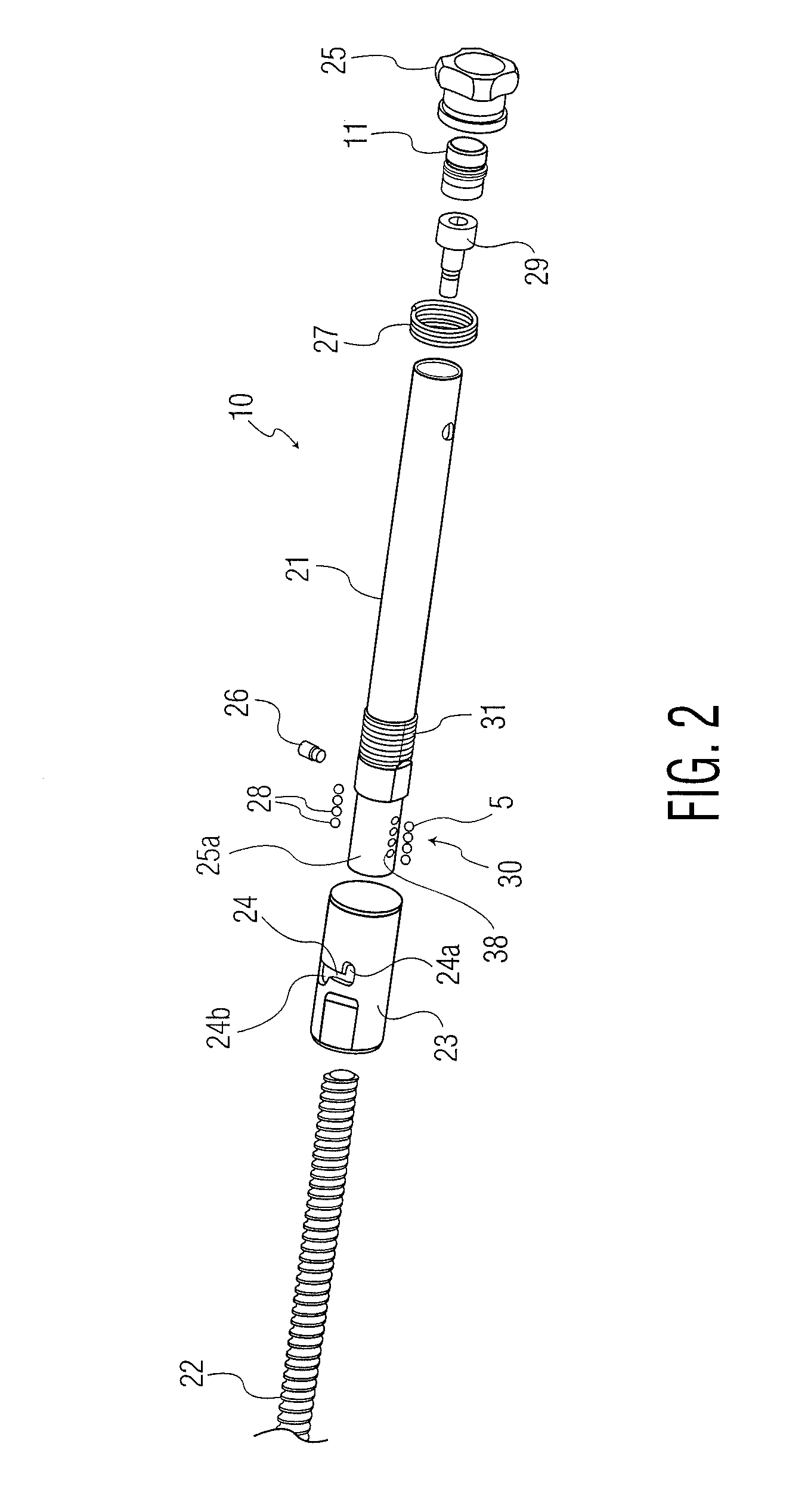
[0035]Referring to FIG. 1 there is shown a perspective view of a telescopic strut according to the invention generally denoted as 10. The telescopic strut comprises two free ends 11 and 12, which include coupling elements 100 and 200 being attachment points for connecting the strut to two external rings to be placed around the limb to be treated. The attachment coupling elements 100 and 200 according to this embodiment preferably comprise ball joints as will be discussed below, but this entirely depends on the kind of fixation element for which the rod is used.

[0036]FIG. 1 shows the main components of the telescopic strut. There is an outer tube tubular element 21 having a bore in which the threaded rod 22 is partially located. Tube 21 has a bore therein for receiving rod 22 the bore can be only partially through tubular element 21 leaving a solid end adjacent coupling 200. The outer tube 21 has mating thread elements 30 for engaging threaded rod 222 which is located within a sleeve...


PUM


Abstract

A telescopic strut for use with an external fixator comprising an axially extending rod; an axially extending tube moveably recurring the rod for varying the length of the rod and tube combination along a longitudinal axis; the tube having first and second ends, the second end having a pin extending therethrough; a locking system mounted on the tube first end for adjusting the position of the rod in the tube and fixing the length of the rod and tube combination; a coupling element having a tubular sleeve with a threaded outer surface mounted on an outer surface of the second end of the tube, the sleeve having two diametrically opposed slots receiving the pin and an adjustment element threadably mounted on the sleeve outer surface for axial movement along the axis, the adjustment element having a surface contacting the pin to limit the movement of the pin in the slots.

Description

CROSS-REFERENCE TO RELATED APPLICATIONS[0001]This application is a continuation of U.S. application Ser. No. 13 / 589,624 filed Aug. 20, 2012, the disclosure of which is incorporated herein by reference.BACKGROUND OF THE INVENTION[0002]The invention relates to a telescopic strut for an external fixator, especially for use with an external ring fixator.[0003]A plurality of compression-distraction apparatus have been designed and improved by Ilizarov and his group using two external rings to be placed around the limb to be fixed. There are usually at least two such rings, one proximal and one distal ring, which are connected with a plurality of struts or rods. Preferably, these struts are linked to the rings in a way that the attachment points can be pivoted and the length of the strut can be varied to enable adjustment of the external fixation rings.[0004]Ilizarov has also provided some improvements for said systems. European Patent No. 0 377 744 shows a telescopic strut for such an ex...

Claims


Application Information

Patent Timeline
Patent Type & Authority Applications(United States)
IPC IPC(8): A61B17/66
CPCA61B17/66A61B17/62
Inventor LEHMANN, PHILIPPEBOUQUET, JOEL
Owner STRYKER EURO OPERATIONS HLDG LLC
Why Eureka
Try Eureka