
Performing simultaneous operations on multiple wellbore locations using a single mobile drilling rig

a mobile drilling rig and simultaneous operation technology, applied in the direction of sealing/packing, wellbore/well accessories, ways, etc., can solve the problems of significant impact on the overall drilling cost at a given time and the substantial idleness of the rig

Active Publication Date: 2015-04-02
NAT OILWELL VARCO LP
View PDF16 Cites 20 Cited by
  • Summary
  • Abstract
  • Description
  • Claims
  • Application Information

AI Technical Summary

Benefits of technology

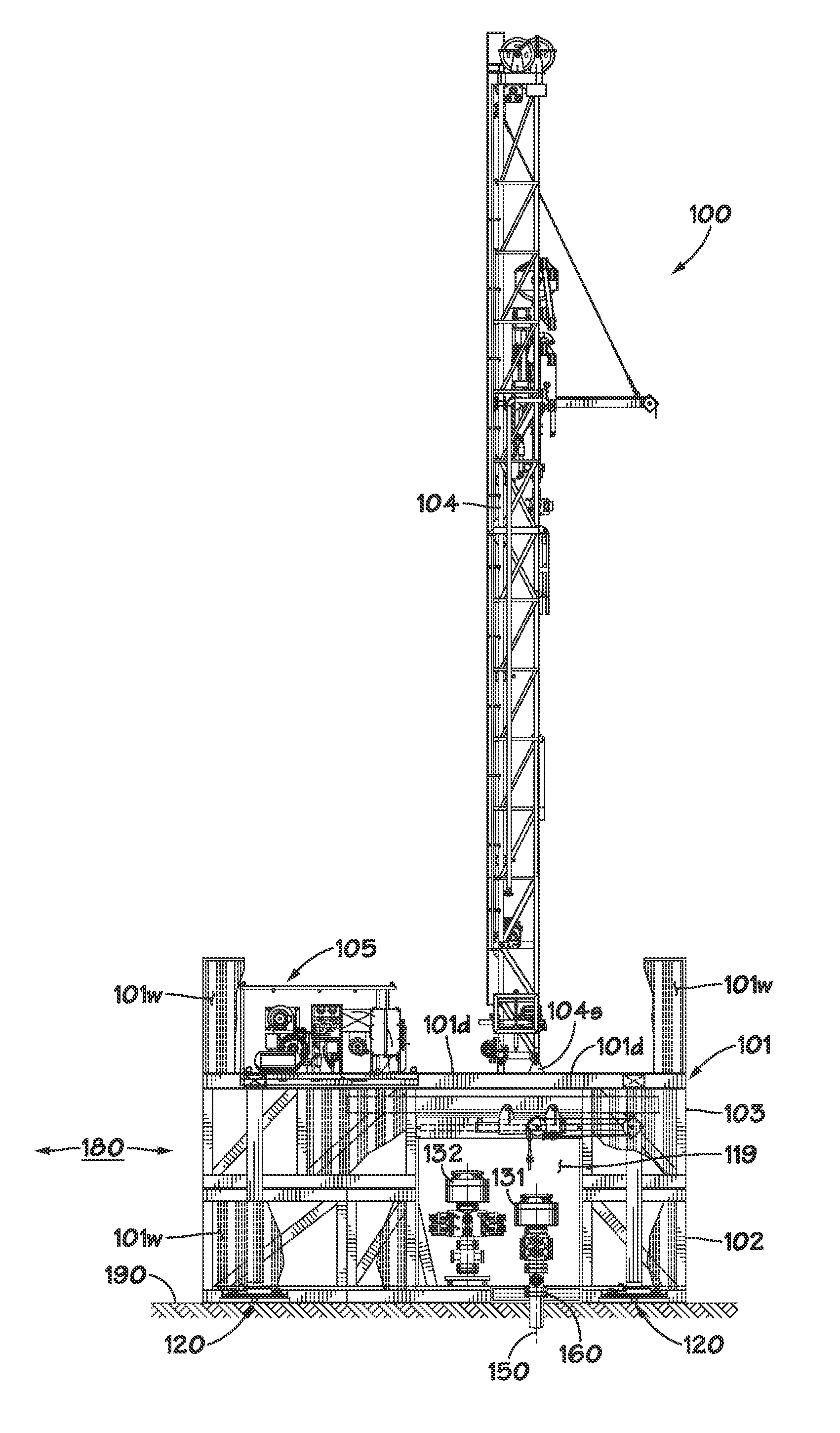
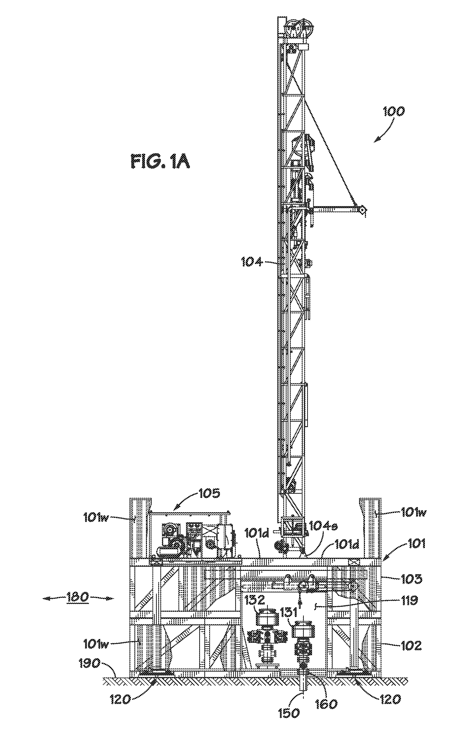
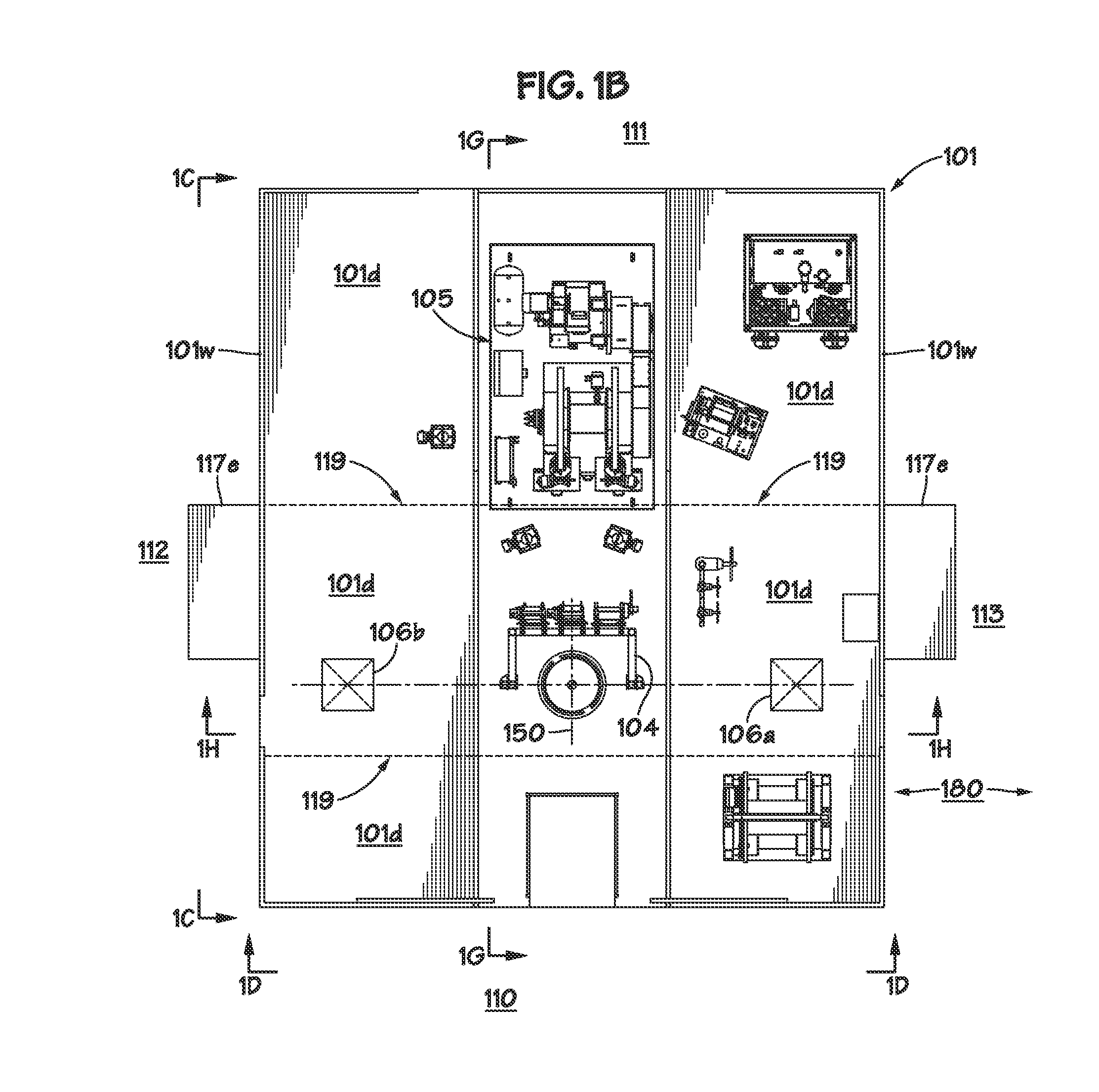
The patent describes a system and method for using a mobile drilling rig to perform multiple operations on multiple wellbores simultaneously. The system includes a substructure that can be positioned above multiple wellbore locations, allowing for simultaneous drilling, wellbore preparation, and wellbore completion operations. The system also includes equipment movement means for moving pressure control equipment between positions proximate each wellbore location while the drilling rig is performing operations on a first wellbore location. The method involves positioning the substructure at the wellbore drilling site, positioning a first blowout preventer on a first wellhead, performing a first on-line drilling operation through the first blowout preventer, moving the second blowout preventer to a second wellhead, and performing a second on-line drilling operation on the second wellbore location through the second blowout preventer. The technical effects of the patent include improved efficiency and productivity in wellbore drilling operations.

Problems solved by technology

Additionally, while the drilling rig is actively working during the casing phase of completion operations, that is, when the casing is being run into the borehole, the drilling rig is again standing substantially idle above the wellbore during cementing operations, as drilling operations on subsequent deeper wellbore sections cannot commence until the cement has been pumped into place, and sufficient time has passed to allow the cement to set up.
The additional flat time associated with the wellbore preparation and completion phases of the overall drilling program may thus have a significant impact on overall drilling costs at a given pad drilling site.

Method used


Image

  • Performing simultaneous operations on multiple wellbore locations using a single mobile drilling rig
  • Performing simultaneous operations on multiple wellbore locations using a single mobile drilling rig
  • Performing simultaneous operations on multiple wellbore locations using a single mobile drilling rig

Examples


Embodiment Construction

[0033]Various illustrative embodiments of the present subject matter are described below. In the interest of clarity, not all features of an actual implementation are described in this specification. It will of course be appreciated that in the development of any such actual embodiment, numerous implementation-specific decisions must be made to achieve the developers' specific goals, such as compliance with system-related and business-related constraints, which will vary from one implementation to another. Moreover, it will be appreciated that such a development effort might be complex and time-consuming, but would nevertheless be a routine undertaking for those of ordinary skill in the art having the benefit of this disclosure.

[0034]The present subject matter will now be described with reference to the attached figures. Various systems, structures and devices are schematically depicted in the drawings for purposes of explanation only and so as to not obscure the present disclosure ...


PUM


Abstract

A system is disclosed that includes a drilling rig having a substructure, the drilling rig being adapted to be positioned above a plurality of wellbore location such that each of the plurality of wellbore locations is simultaneously positioned below the substructure, equipment movement means for moving pressure control equipment between positions proximate each of the plurality of wellbore locations, the equipment movement means being adapted to move the pressure control equipment between the positions while the drilling rig is performing a rig operation on at least a first one of the plurality of wellbore locations, and equipment positioning means for positioning pressure control equipment on one or more of the plurality of wellbore locations, the equipment positioning means being adapted to position the pressure control equipment on a second one of the plurality of wellbore locations while the rig operation is being performed on the first wellbore location.

Description

BACKGROUND[0001]1. Field of the Disclosure[0002]The present subject matter is generally directed to performing drilling activities with mobile drilling rig assemblies, and in particular, to systems and methods that may be used to perform simultaneous operations on multiple wellbore locations with a single mobile drilling rig.[0003]2. Description of the Related Art[0004]In some land-based oil and gas drilling applications, the drilling operations that are performed at a given oilfield drilling site may involve drilling a plurality of relatively closely spaced wellbores, sometimes referred to as “pad” drilling operations. In pad drilling, the distance between adjacent wellbores may be as little as approximately 5-6 meters (16-20 feet) or even less, and the wellbores are oftentimes arranged in a two-dimensional grid pattern, such that rows and columns of wellbores are disposed along lines that run substantially parallel to an x-axis and a y-axis, respectively.[0005]In such pad drilling...

Claims


Application Information

Patent Timeline
Patent Type & Authority Applications(United States)
IPC IPC(8): E21B15/00E21B33/14E01B5/02E21B33/06
CPCE21B15/003E01B5/02E21B33/14E21B33/06
Inventor THIESSEN, JAY JOHN
Owner NAT OILWELL VARCO LP
Learn More