Filter element wave seal gland

Active Publication Date: 2015-04-16
PARKER INTANGIBLES LLC
View PDF3 Cites 34 Cited by
  • Summary
  • Abstract
  • Description
  • Claims
  • Application Information

AI Technical Summary

Benefits of technology

The present invention provides a sealing mechanism for a gas detector that ensures a good seal and prevents leakage even during high differential pressures. The sealing mechanism consists of tabs and slots on the end cap and the socket, which make it easy to position and install the element in the socket. The technical effects of the invention include improved seal retention, quick engagement between the end cap and socket, and a strong seal even at high differential pressures.

Problems solved by technology

In other words, the canister cannot be properly screwed onto the head when the element is out of rotational alignment with the diaphragm, as the expanded element / diaphragm interface prevents the canister from being tightened-down.

Method used


Image

  • Filter element wave seal gland
  • Filter element wave seal gland
  • Filter element wave seal gland

Examples


Embodiment Construction

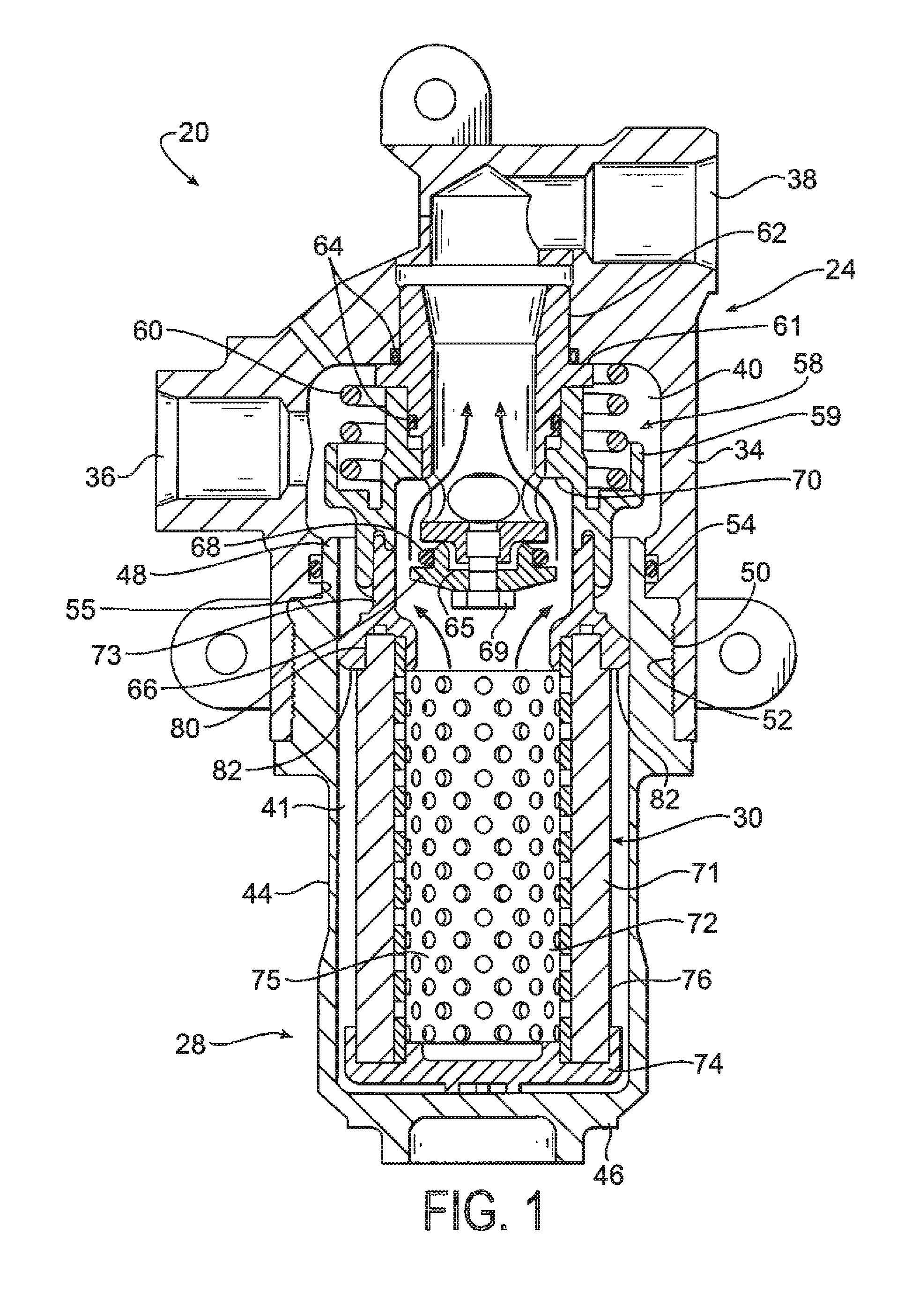
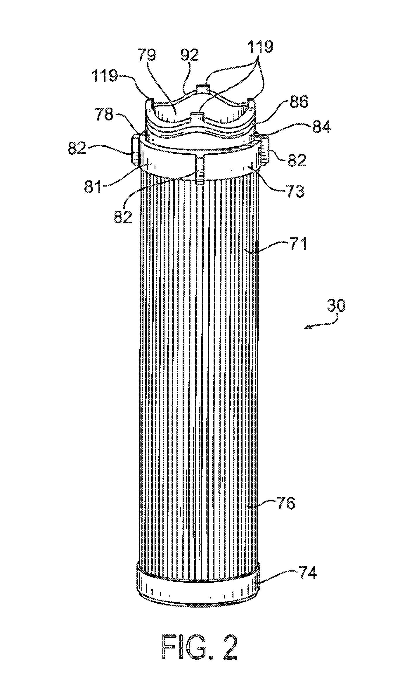
[0047]Referring to the Figures, and initially to FIG. 1, a filter module constructed according to the present invention is shown generally at 20. Filter module 20 can be used in a variety of applications, for example, hydraulic filter applications, where it is necessary or desirable to remove particulate and / or other contaminants from a hydraulic fluid stream. Module 20 generally includes a head assembly, indicated generally at 24, a cup-shaped bowl or canister, indicated generally at 28, and a filter element, indicated generally at 30, which is received and supported in bowl 28 and removes the contaminants and particulate in the fluid stream as it passes therethrough.

[0048]The head assembly 24 of the module includes a body 34 with an inlet port 36 which can be connected to receive fluid to be filtered from the system, and an outlet port 38 which can be connected to direct filtered fluid back to the system. Inlet port 36 directs incoming fluid into an inlet cavity 40 in the body whe...


PUM


Abstract

Provided is a cartridge assembly having first and second cartridges sealed by an interface member having a first sealing member along a radially outer surface thereof having a non-planar geometry around the outer surface and a second sealing member along the radially outer surface having a non-planar geometry around the outer surface. The sealing members may each have a repeating, undulating, non-planar geometry around the outer surface. The cartridges have ends with matching geometries to allow the cartridges to engage in surface-to-surface relation around their entire extents to create with the interface member an air tight seal.

Description

RELATED APPLICATIONS[0001]This application is a continuation-in-part of U.S. patent application Ser. No. 13,305,894 filed Nov. 29, 2011, which claims the benefit of U.S. Provisional Application No. 61 / 433,611 filed Jan. 18, 2011. The entire disclosures of these applications are hereby incorporated by reference.FIELD OF INVENTION[0002]The present invention relates generally to filter elements and filter modules, and to the interface between the element and a corresponding mating component.[0003]In some filtration applications, a replaceable filter element has an end cap which is connected to the head of a filter module. The module includes a canister which receives the element, and inlet and outlet ports in the head which direct fluid into and out of the module. The fluid passes through the filter element, which separates particles and other contaminants from the fluid which is then returned to the operating system. In order for the filter element to properly function and not leak, a...

Claims


Application Information

Patent Timeline
IPC IPC(8): B01D46/00
CPCB01D46/0023B01D46/0004B01D35/153B01D2201/295B01D2201/296B01D2201/4046B01D2201/347B01D29/54B01D29/58B01D46/62
Inventor THOMPSON, DOMINICRAPIN, DANIEL P.
Owner PARKER INTANGIBLES LLC
Why Eureka
Try Eureka