Methods and systems for self-aligning high data rate communication networks

a communication network and high data rate technology, applied in the direction of antenna details, electrical equipment, antennas, etc., can solve the problems of limiting the size and type of communication equipment, avs are particularly sensitive to weight, size, power (swap) constraints, etc., and achieves less signal power, high data rate communication, and small swap components

Inactive Publication Date: 2015-04-30
CHARLES STARK DRAPER LABORATORY
View PDF11 Cites 22 Cited by
  • Summary
  • Abstract
  • Description
  • Claims
  • Application Information

AI Technical Summary

Benefits of technology

[0007]High data rate communication is desirable between mobile vehicles, for example, to enable the sharing of data between airborne vehicles (AV) flying within a given proximity. AVs, however, are particularly sensitive to weight, size, and power (SWaP) constraints. These SWaP constraints limit the size and type of communication equipment that can be supported by the AV. In this environment, highly directional antennas require less signal power to be transmitted and subsequently smaller SWaP components can be employed. A narrower beam width (i.e., concentrating the signal power emitted) may require antenna alignment to create and sustain communication links within the network. Accordingly, systems and methods for a self aligning high data rate communication network are provided. Various aspects of a self aligning high data rate communication network as disclosed herein enable one or more high data rate communication links to be established between a plurality of mobile systems employing one or more directional antennas.

Problems solved by technology

AVs, however, are particularly sensitive to weight, size, and power (SWaP) constraints.
These SWaP constraints limit the size and type of communication equipment that can be supported by the AV.

Method used


Image

  • Methods and systems for self-aligning high data rate communication networks
  • Methods and systems for self-aligning high data rate communication networks
  • Methods and systems for self-aligning high data rate communication networks

Examples


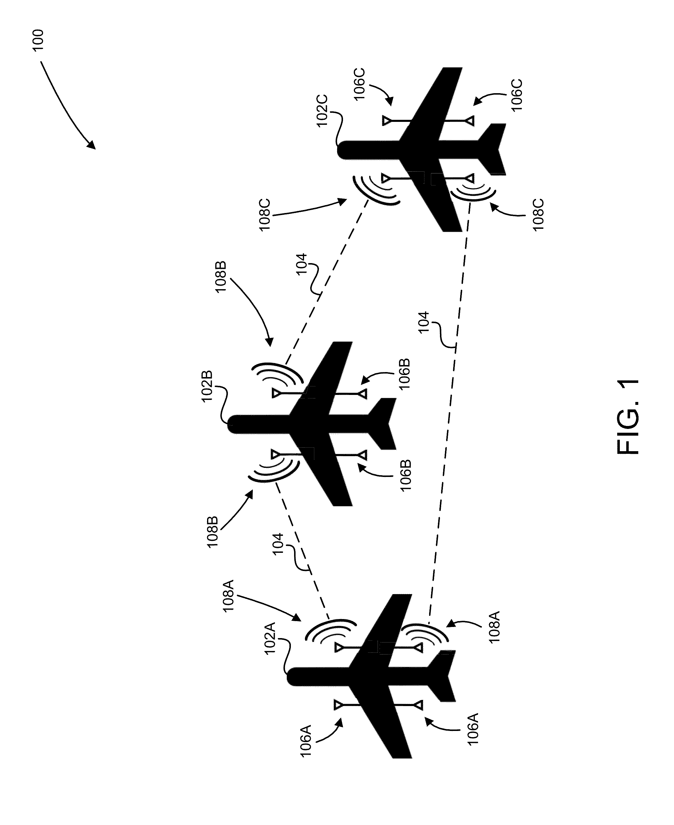
example communication

Management System

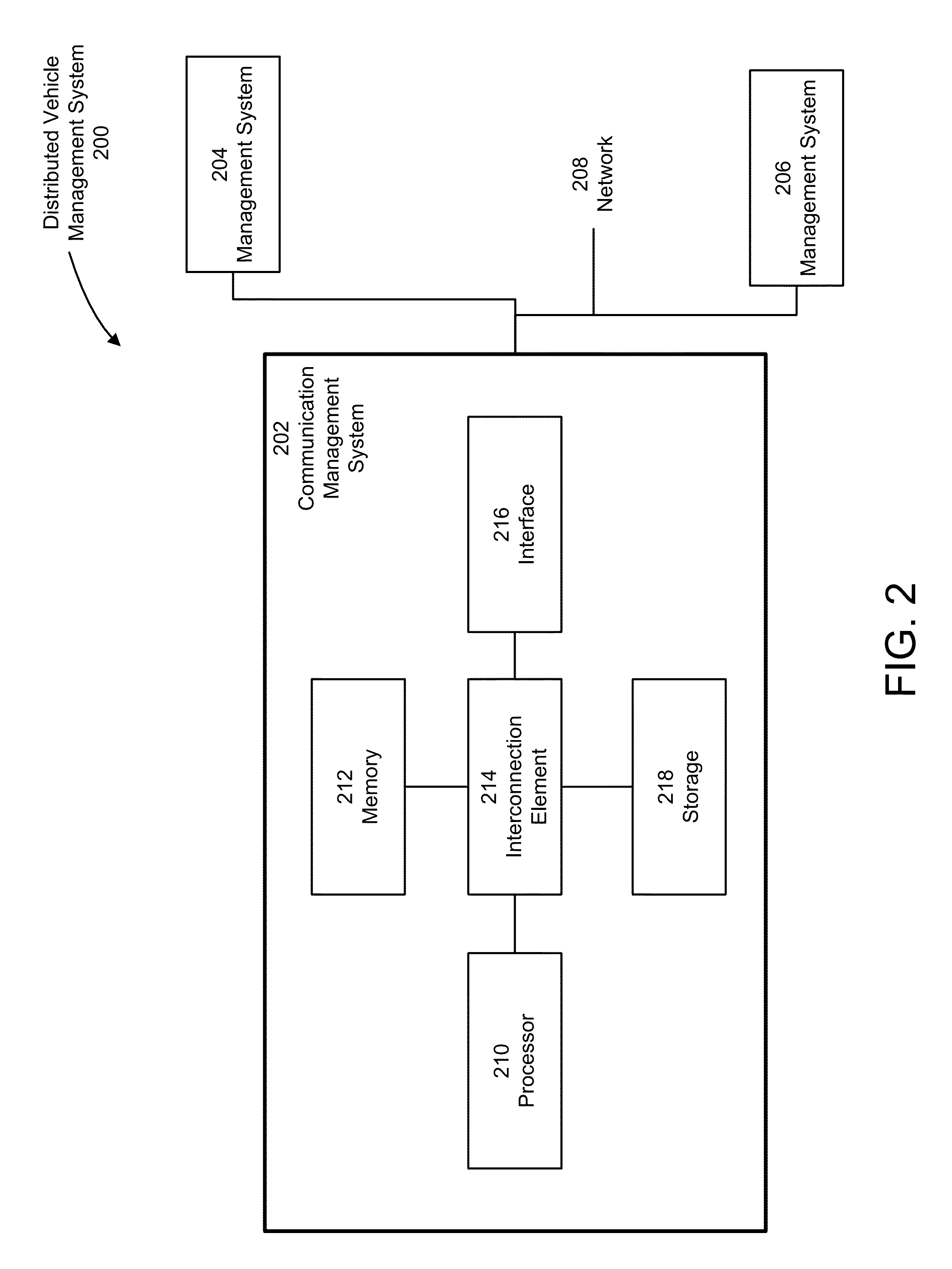
[0072]Various aspects and functions described herein may be implemented as specialized hardware or software components executing in one or more management systems. Further, aspects may be located on a single management system or may be distributed among a plurality of management systems connected to one or more communication networks. For example, various aspects and functions may be distributed among one or more management systems configured to monitor and / or control a specific vehicle system (e.g., the communication system) as part of a distributed system. Consequently, examples are not limited to executing on any particular system or group of systems. Further, aspects and functions may be implemented in software, hardware or firmware, or any combination thereof. Thus, aspects and functions may be implemented within methods, acts, systems, system elements and components using a variety of hardware and software configurations, and examples are not limited to any pa...


PUM


Abstract

A communication system is provided. The communication system includes a directional antenna, an antenna steering system to steer the directional antenna, a memory, and one or more processors coupled to the memory, the directional antenna, and the antenna steering system. The one or more processors are configured to identify a communication target and state information associated with the communication target, instruct the antenna steering system to steer the at least one directional antenna towards the communication target based on the state information, instruct the antenna steering system to perform a received power scan within a scan area to determine a maximum received power direction associated with a signal transmitted from the communication target, and track the maximum received power direction.

Description

CROSS REFERENCE TO RELATED APPLICATIONS[0001]This application claims priority under 35 U.S.C. §119(e) to co-pending U.S. Provisional Application No. 61 / 895,440, titled “METHODS AND SYSTEMS FOR SELF-ALIGNING HIGH DATA RATE COMMUNICATION NETWORKS,” filed on Oct. 25, 2013, which is hereby incorporated herein by reference in its entirety.FEDERALLY SPONSORED RESEARCH[0002]This invention was made with U.S. government support under Government Contract Number FA8750-12-C-0255 awarded by Department of the Air Force. The U.S. government has certain rights in this invention.BACKGROUND[0003]1. Technical Field[0004]Aspects of the present disclosure relate to methods and systems for high data rate communication networks.[0005]2. Discussion[0006]High data rate wireless communication networks are desirable in a variety of circumstances including wireless communication networks comprising any number of mobile systems (e.g., ground vehicles, ships, airborne vehicles). Such high data rate communicatio...

Claims


Application Information

Patent Timeline
Patent Type & Authority Applications(United States)
IPC IPC(8): H01Q3/34
CPCH01Q3/34H01Q1/1257H01Q3/08H01Q15/08
Inventor CHIBANE, CHERIFLIM, SUNGYUNGEASTERLY, TIMOTHY B.PLUMP, JOHN M.MCFARLAND, WILLIAM W.SINGH, LEENA
Owner CHARLES STARK DRAPER LABORATORY
Why Eureka
Try Eureka