Downhole Tools, System and Methods of Using

Inactive Publication Date: 2015-05-14
PEAK COMPLETION TECH
View PDF6 Cites 34 Cited by
  • Summary
  • Abstract
  • Description
  • Claims
  • Application Information

AI Technical Summary

Benefits of technology

The present patent describes a downhole tool used in oil and gas wells that can be used to test the pressure of the tubing installed in the well. The tool has a chamber that is in fluid communication with the interior of the tubing, but isolated from the fluid pressure inside the tubing. The tool is designed to shift its position in response to the pressure differential between the interior and exterior of the tubing, allowing fluid pressure to be applied to the tubing without transferring it to the chamber. The tool can be used in a series of other tools to actuate them in response to fluid pressure. The technical effect of the invention is to provide a tool that can safely and accurately test the pressure of tubing in a well without risking damage to the well equipment.

Problems solved by technology

One detriment to these pressure tests is the necessity for a closed toe.
While formation characteristics, cement, or other factors may still restrict fluid flow, the presence of such factors do not alleviate the desirability or necessity for opening the toe of the tubing.
Commonly, the toe is opened by positioning a perforating device in the toe and either explosively or abrasively perforating the tubing to create one or more openings.
Perforating, however, requires additional time and equipment that increase the cost of the well.

Method used


Image

  • Downhole Tools, System and Methods of Using
  • Downhole Tools, System and Methods of Using
  • Downhole Tools, System and Methods of Using

Examples


Embodiment Construction

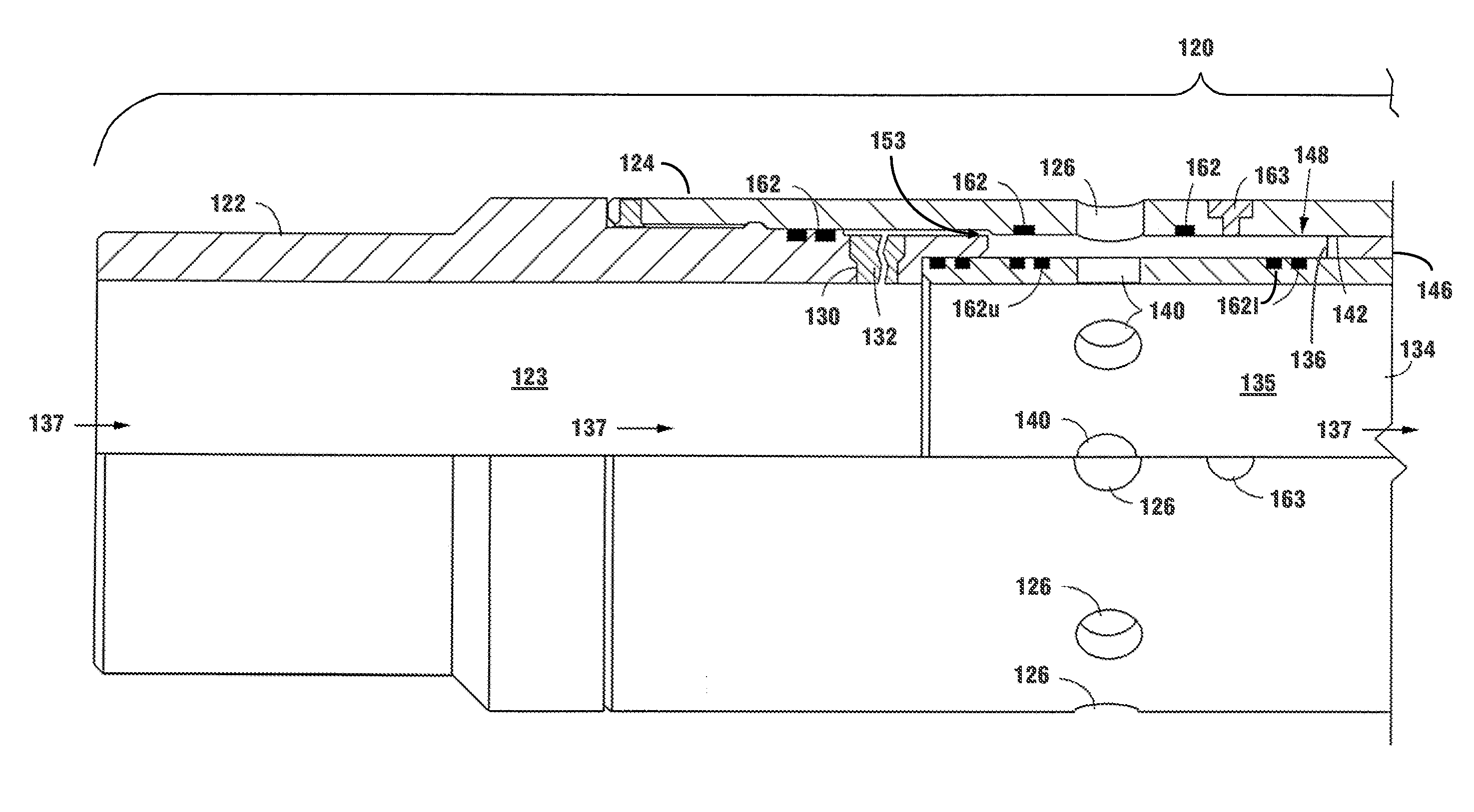
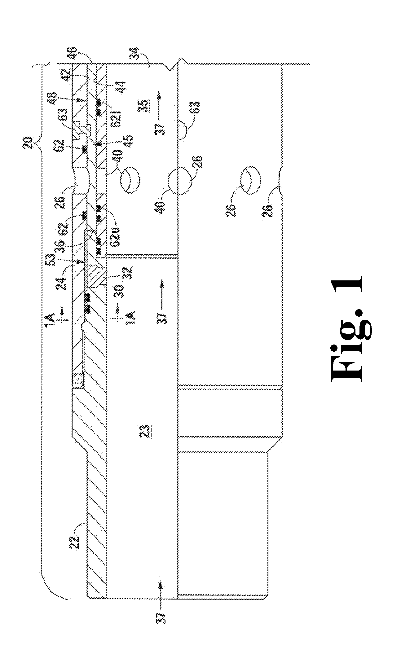
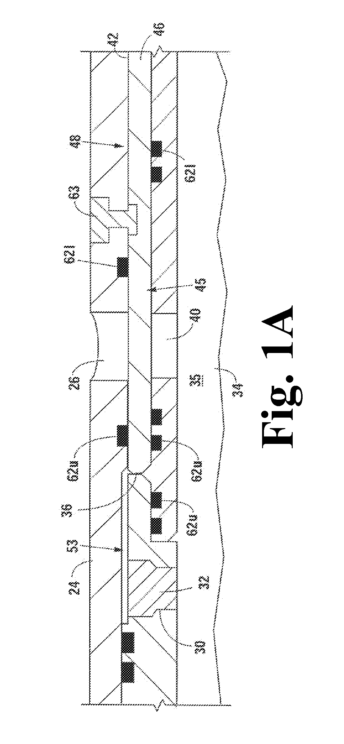
[0010]The described embodiments of the present disclosure address the problems associated with the closed toe required for pressure testing tubing installed in a well. Further, in one aspect of the present disclosure, a chamber, such as a pressure chamber, air chamber, or atmospheric chamber, is in fluid communication with at least one surface of the shifting element, which may be a shifting sleeve, of the device. The chamber is isolated from the interior of the tubing such that fluid pressure inside the tubing is not transferred to the chamber. A second surface of the shifting sleeve is in fluid communication with the interior of the tubing. Application of fluid pressure on the interior of the tubing thereby creates a pressure differential across the shifting element, applying force tending to shift the shifting element in the direction of the pressure chamber, atmospheric chamber, or air chamber.

[0011]In a further aspect of the present disclosure, the shifting sleeve is encased in...


PUM


Abstract

The present disclosure relates to downhole tools, including downhole valves, which actuate via a pressure differential created across a shifting element having one or more pressure surfaces isolated from fluid, and fluid pressure, flowing through the interior flowpath. Embodiment downhole tools of the present disclosure may actuate in response to, among other signals, fluid pressure in the interior flowpath of the tool and fluid pressure communicated to a pressure surface of the shifting sleeve from the exterior of the tool. Certain embodiments may also have an outlet connector whereby fluid pressure from the downhole tool may be communicated to its exterior, including to additional tools in the tubing strings via flowlines connecting the two tools. Isolation of the shifting element from the interior flowpath may be accomplished using a frangible, shiftable, degradable or other members which may be moved from a closed state to an open state in response to fluid conditions in the interior flowpath.

Description

CROSS-REFERENCES TO RELATED APPLICATIONS[0001]This original non-provisional application claims the benefit of U.S. Provisional Patent Application Ser. No. 61 / 885,615; is a Continuation in Part, and claims the benefit, of U.S. patent application Ser. No. 14 / 211,122, entitled Downhole Tools System and Method of Using filed Mar. 14, 2014, which claims the benefit of U.S. Provisional Patent Application Ser. No. 61 / 801,937, entitled “Downhole Tools System and Method of Using” filed on Mar. 15, 2013; and of U.S. Provisional Patent Application Ser. No. 61 / 862,766, entitled “Downhole Tools System and Method of Using” filed on Aug. 16, 2013; and is a Continuation in Part of U.S. patent application Ser. No. 13 / 462,180, filed May 2, 2012 entitled “Downhole Tool,” which claims the benefit of U.S. Provisional Patent Application Ser. No. 61 / 481,483 filed on May 2, 2011. Each of the foregoing references are incorporated herein by reference in their entiretySTATEMENT REGARDING FEDERALLY SPONSORED R...

Claims


Application Information

Patent Timeline
IPC IPC(8): E21B34/14E21B33/13E21B47/00E21B34/06
CPCE21B34/14E21B34/063E21B2034/007E21B47/0006E21B33/13E21B34/103E21B2200/06
Inventor HOFMAN, RAYMONDMUSCROFT, WILLIAM SLOANE
Owner PEAK COMPLETION TECH
Why Eureka
Try Eureka