System for installation of well stimulating apparatus downhole utilizing a service tool string

a technology of service tool string and well stimulation apparatus, which is applied in the directions of sealing/packing, wellbore/well accessories, fluid removal, etc., can solve the problem of time-consuming process

Inactive Publication Date: 2001-04-17
SCHLUMBERGER TECH CORP
View PDF15 Cites 151 Cited by
  • Summary
  • Abstract
  • Description
  • Claims
  • Application Information

AI Technical Summary

Problems solved by technology

Such a process is time consuming and requires a rig for running in the production string and for removing the work string after the fracturing process has been completed.

Method used


Image

  • System for installation of well stimulating apparatus downhole utilizing a service tool string
  • System for installation of well stimulating apparatus downhole utilizing a service tool string
  • System for installation of well stimulating apparatus downhole utilizing a service tool string

Examples


Embodiment Construction

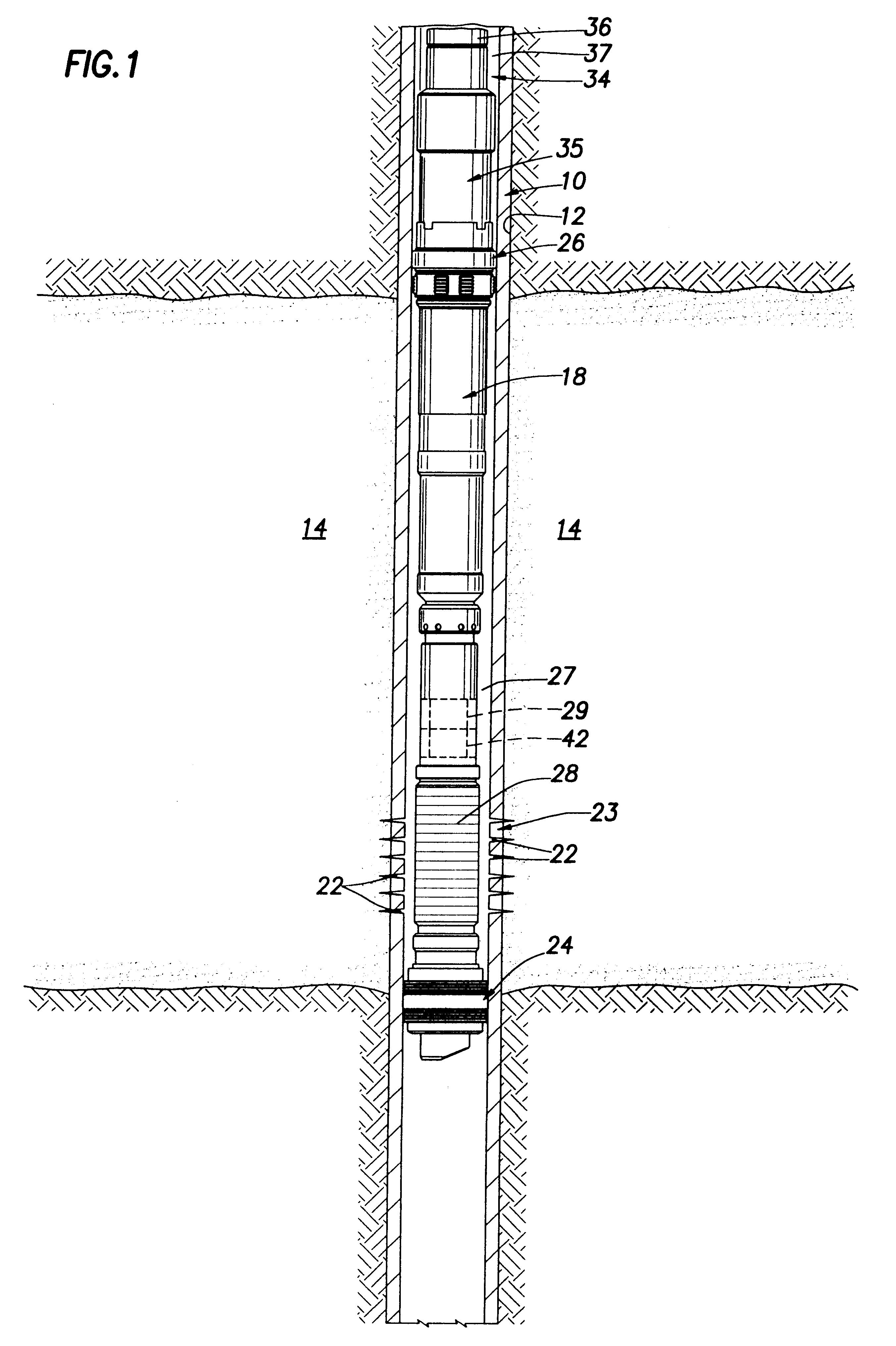
Referring now to the drawings for a better understanding of the invention, and more particularly to FIG. 1, a casing 10 is shown mounted within a bore hole 12 in the earth formation having a production or zone of interest at 14. Casing 10 is normally secured by cement within borehole 12 as well known.

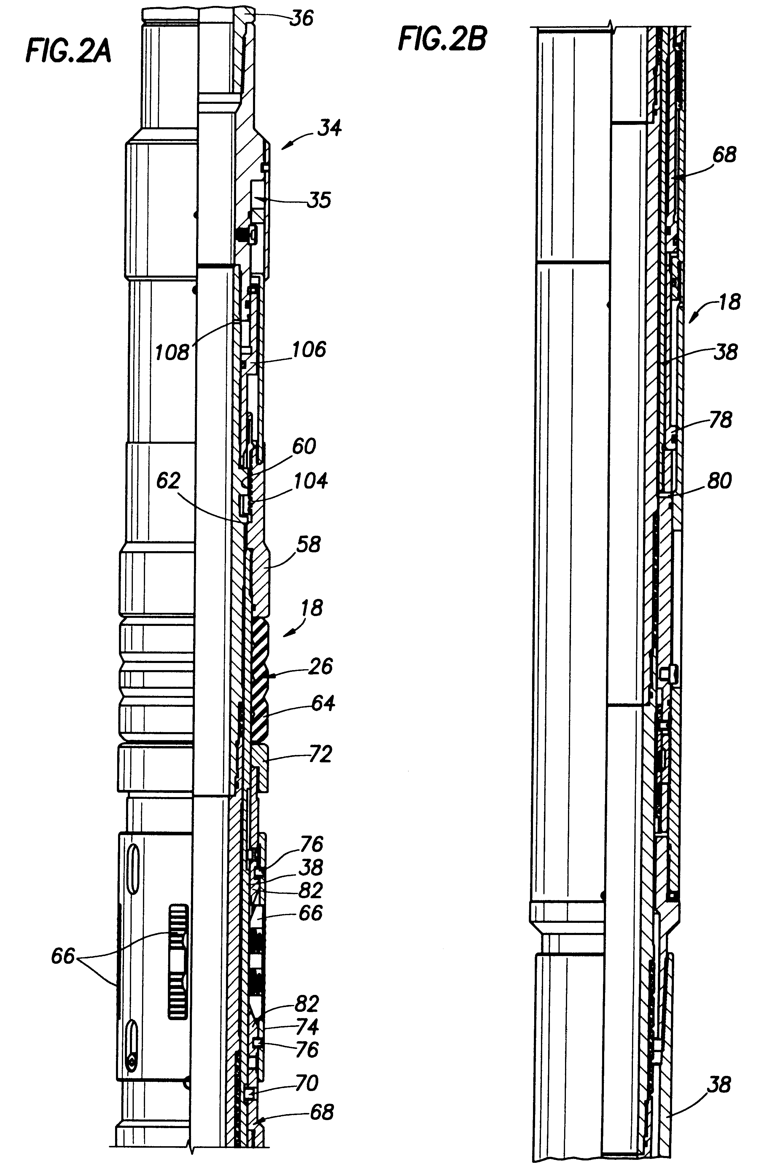
A bottom hole assembly shown generally at 18 is received within casing 10. Casing 10 has a perforated casing section 23 including perforations 22. Perforated casing section 23 is normally perforated by a separate perforating string having a perforating gun on its lower end prior to the insertion of bottom hole assembly 18.

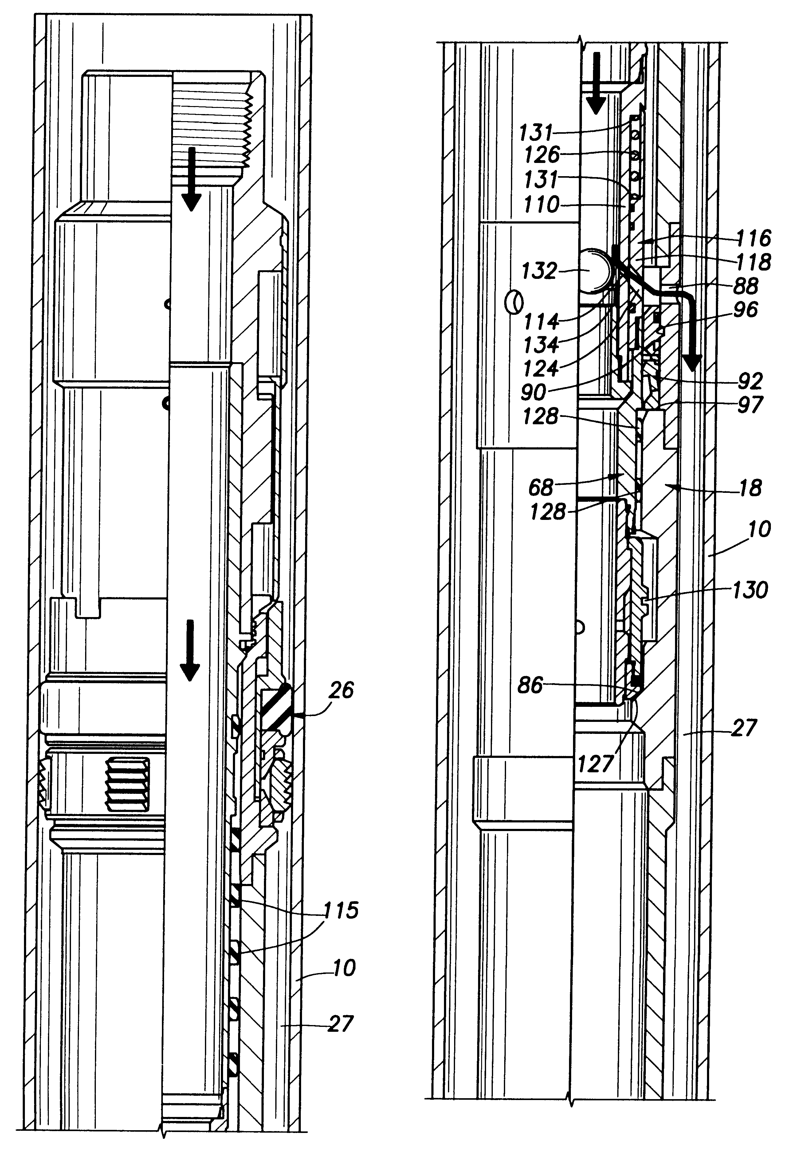
Bottom hole assembly 18 include a lower, packer assembly generally indicated at 24 and an upper packer assembly generally indicated at 26 for isolation of the production zone 14. An annulus 27 is defined between bottom hole assembly 18 and casing 10. A gravel pack screen indicated at 28 is positioned between packers 24, 26 adjacent perforations 22. An equalizing valve ...


PUM


Abstract

A service tool string (34) is releasably attached to a bottom hole assembly (18) and forms a production string as well as a work string. The tool (35) has a mandrel (102) and a slide valve assembly (68) mounted on the mandrel for relative sliding movement. Crossover ports (114, 124) are provided in the mandrel (102) and the slide valve assembly (68). Slide valve assembly (68) moves by gravity and spring action when not contacted by the bottom hole assembly (18) to a position in which ports (114, 124) are blocked as shown in FIG. 7B. Upon contact of slidable valve assembly (68) with the bottom hole assembly (18), slide valve assembly is moved upwardly for alignment of ports (114, 124) as shown in FIGS. 5B and 6B. An equalizing valve (29) as shown in FIGS. 10-12 is effective to equalize the fluid pressure within the bottom hole assembly (18) with the fluid pressure outside the perforated casing section (23) so that in a reverse position as shown in FIG. 7B, the service tool (35) can be lifted to a position above the upper packer assembly (26) and above the bottom hole assembly (18). A diverter ball (132) seated on a ball catcher (134) is effective to divert the fracturing fluid outwardly through crossover ports (114, 124) as shown in FIG. 6B for downward flow through the annulus (27) into the formation adjacent the perforated casing section (23).

Description

1. Field of the InventionThis invention relates to a system including an apparatus and method for the installation of well stimulation apparatus downhole utilizing a service tool string for gravel packing a downhole formation, and more particularly to such a system in which the tool string forms the production string for production of the downhole formation to provide a one trip gravel pack and production system.2. Background of the InventionHeretofore, it has been common to provide well stimulating apparatus for fracturing a formation in which the apparatus is lowered within a well bore on the lower end of a service tool on a work string. The stimulating apparatus for hydraulic fracturing with a proppant, such as a sand slurry, may include a lower perforating gun which is utilized for perforating the well casing at the production zone, and a production screen or filter is then positioned. After perforation of the well casing, a gravel packing packer assembly is lowered by a service...

Claims


Application Information

Patent Timeline
Patent Type & Authority Patents(United States)
IPC IPC(8): E21B33/12E21B43/26E21B43/10E21B43/02E21B43/04E21B33/124E21B43/25
CPCE21B33/124E21B43/045E21B43/10E21B43/26
Inventor ACHEE, JR., TIMOTHY T.BISSONETTE, HAROLD S.DANCAUSE, CHARLES M.
Owner SCHLUMBERGER TECH CORP
Why Eureka
Try Eureka