Reducing fluid pressure spikes in a pumping system

a technology pumping systems, applied in the direction of positive displacement liquid engines, pump parameters, borehole/well accessories, etc., can solve the problems of fluid pressure spikes, equipment failures, piping, hoses, etc., and increase the size, weight, and cost of the pumping system

Active Publication Date: 2019-08-27
LIBERTY OILFIELD SERVICES LLC
View PDF13 Cites 153 Cited by
  • Summary
  • Abstract
  • Description
  • Claims
  • Application Information

AI Technical Summary

Problems solved by technology

Although reciprocating pumps may operate well at high pressures, the pressurized fluid is discharged in an oscillating manner forming fluid pressure spikes at the pump outlet.
Piping, hose, and equipment failures have been linked to the high-pressure spikes.
Such solutions, however, increase the size, weight, and cost of the pumping systems.

Method used


Image

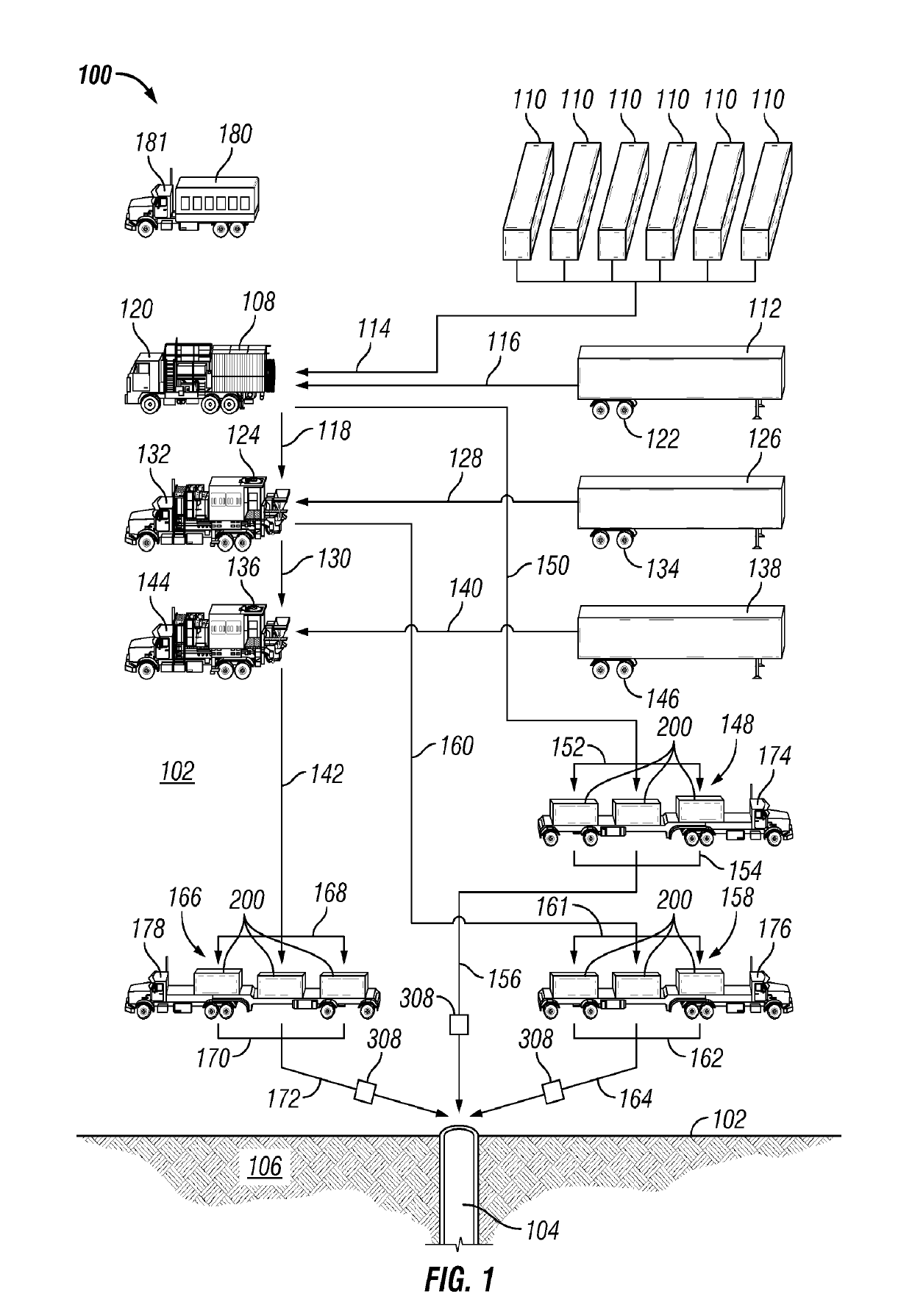
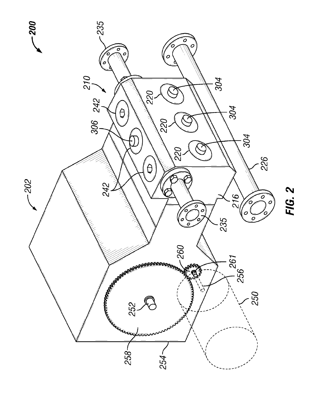
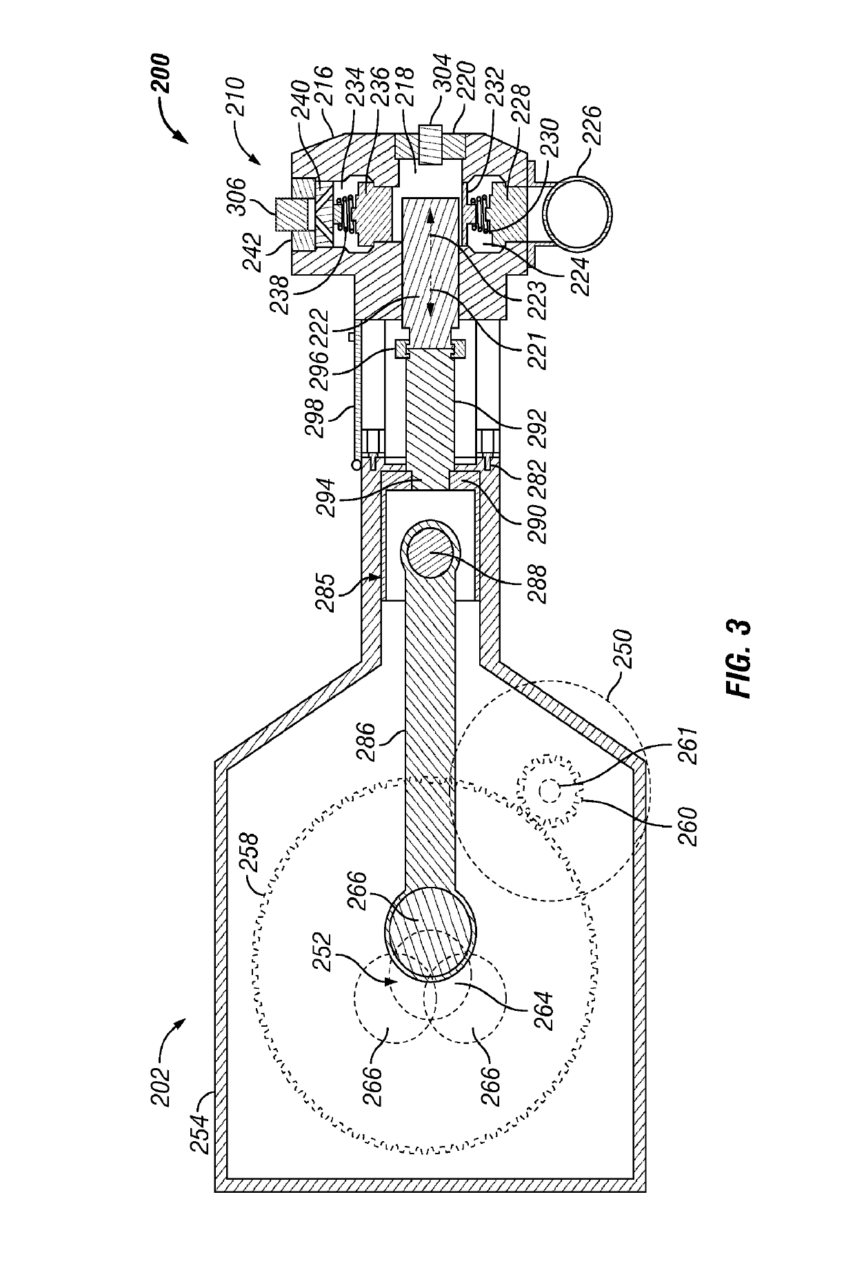
  • Reducing fluid pressure spikes in a pumping system
  • Reducing fluid pressure spikes in a pumping system
  • Reducing fluid pressure spikes in a pumping system

Examples


Embodiment Construction

[0021]It is to be understood that the following disclosure provides many different embodiments, or examples, for implementing different features of various embodiments. Specific examples of components and arrangements are described below to simplify the present disclosure. These are, of course, merely examples and are not intended to be limiting. In addition, the present disclosure may repeat reference numerals and / or letters in the various examples. This repetition is for simplicity and clarity, and does not in itself dictate a relationship between the various embodiments and / or configurations discussed. Moreover, the formation of a first feature over or on a second feature in the description that follows may include embodiments in which the first and second features are formed in direct contact, and may also include embodiments in which additional features may be formed interposing the first and second features, such that the first and second features may not be in direct contact....


PUM


Abstract

A pumping system including a plurality of pumps each having a pump fluid outlet, a drive shaft, a prime mover, and fluid displacing members operatively coupled with the drive shaft. A common fluid conduit may be fluidly coupled with each pump fluid outlet. A control system of the pumping system includes position sensors operable to generate information relating to phase and / or speed of each pump, pressure sensors operable to generate information relating to fluid pressure spikes, and a controller in communication with the position and pressure sensors. The controller is operable to cause the prime movers to adjust the phasing of the pumps with respect to each other, based on the information relating to fluid pressure spikes, and synchronize the speed of the pumps.

Description

CROSS-REFERENCE TO RELATED APPLICATIONS[0001]This application is a 371 National Phase Application of International Patent Application No. PCT / US2015 / 023296, filed Mar. 30, 2015, which claims the benefit of and priority to U.S. Provisional Application No. 61 / 973,050, entitled “Method for Minimizing Pressure Pulsations for Multiple Pumps,” filed Mar. 31, 2014. The entire disclosures of both applications are hereby incorporated herein by reference.BACKGROUND OF THE DISCLOSURE[0002]In oilfield operations, reciprocating pumps are utilized at wellsites for large scale, high-pressure operations. Such operations may include drilling, cementing, acidizing, water jet cutting, and hydraulic fracturing of subterranean formations. In some applications, several pumps may be connected in parallel to a single manifold, flow line, or well. Some reciprocating pumps include reciprocating members driven by a crankshaft toward and away from a fluid chamber to alternatingly draw in, pressurize, and expel...

Claims


Application Information

Patent Timeline
Patent Type & Authority Patents(United States)
IPC IPC(8): F04B1/00F04B23/06F04B23/04F04B51/00F04B49/20F04B49/06F04B17/03E21B43/26F04B11/00F04B17/05
CPCF04B17/03F04B23/06F04B49/065F04B49/20F04B11/0058F04B1/00F04B51/00F04B23/04F04B2205/03F04B2205/05E21B43/2607F04B17/05F04B2201/0201F04B2205/04
Inventor CHONG, JONATHAN WUN SHIUNGCALLAWAY, LEWISHODGSON, KIM
Owner LIBERTY OILFIELD SERVICES LLC
Why Eureka
Try Eureka