
System and Method for Charging Portable Electronic Devices

a portable electronic device and charging system technology, applied in the direction of switch power arrangement, battery overheat protection, safety/protection circuit, etc., can solve the problems of high total power draw, safety considerations and related costs, and the need for special installation, and achieve the effect of safe charging

Active Publication Date: 2015-05-14
FIFTH LABOR INC
View PDF10 Cites 20 Cited by
  • Summary
  • Abstract
  • Description
  • Claims
  • Application Information

AI Technical Summary

Benefits of technology

The present invention is a charging system that can charge multiple appliances from a single power source. The charging system can adjust the charging sequence based on temperature and can be used in places where additional power lines or extension cords are not needed. The system utilizes individual devices that do not need to be continuously charged for an extended period of time, which allows all devices to be fully charged at the end of the charging period. The system can safely charge multiple tablet computers overnight in a single cabinet powered by a single 15 Ampere power outlet. Overall, the charging system provides a convenient and safe way to charge multiple devices from a single power source.

Problems solved by technology

However, there is a major problem with charging such devices: they draw considerable charging current from the power line, and they continue to draw this current even after the device is fully charged.
This creates a problem because a typical charging situation may require that 20-30 devices be charged overnight for use the next day.
This is expensive and must be specially installed.
The use of multiple 15 Ampere outlets usually requires several extension cords (since they are seldom located together), and the total power draw, safety considerations and related cost is considerable.

Method used


Image

  • System and Method for Charging Portable Electronic Devices
  • System and Method for Charging Portable Electronic Devices
  • System and Method for Charging Portable Electronic Devices

Examples


Embodiment Construction

[0033]Set forth below is a description of what is currently believed to be the preferred embodiments or best representative examples of the inventions claimed. Future and present alternatives and modifications to the embodiments and preferred embodiments are contemplated. Any alternatives or modifications which make insubstantial changes in function, purpose, structure or result are intended to be covered by the claims of this patent.

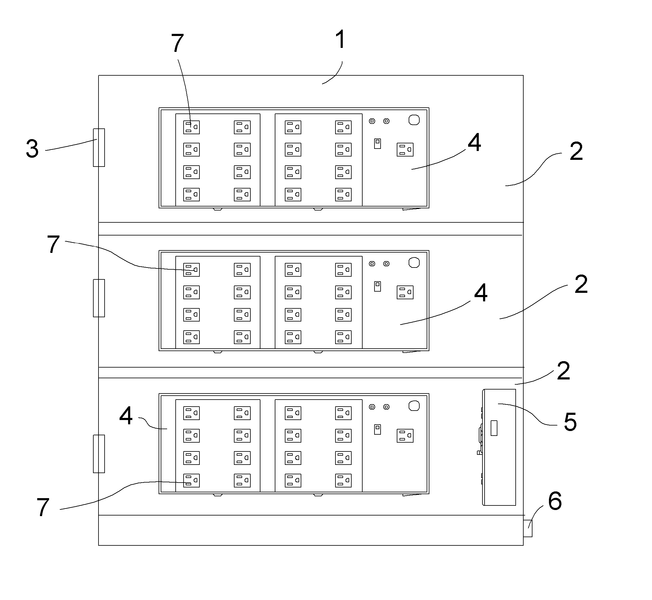
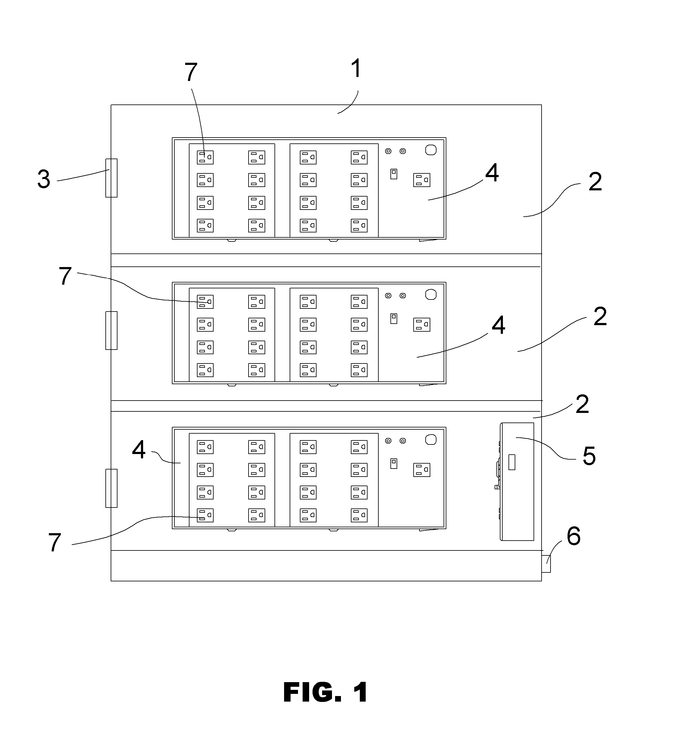
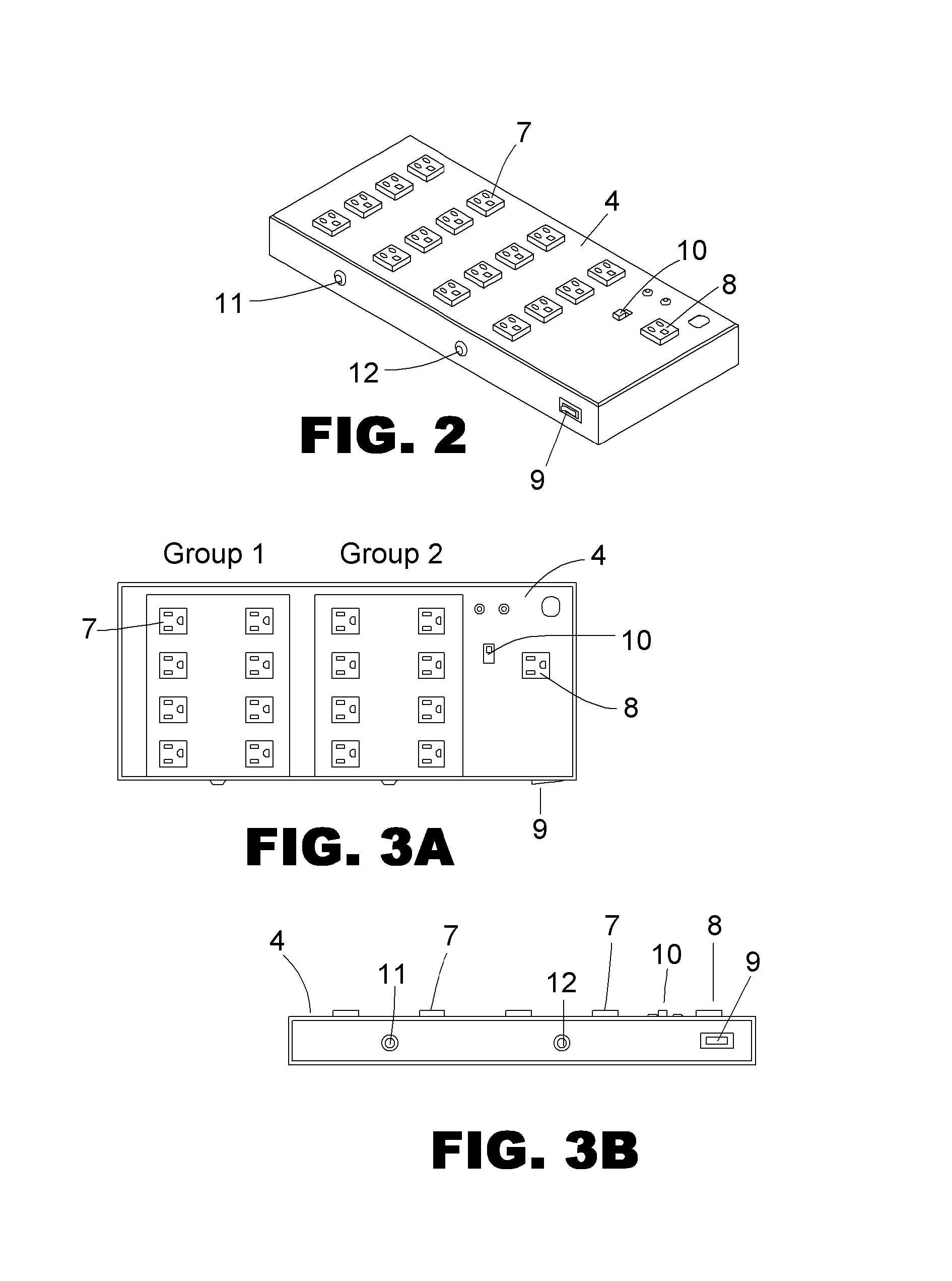
[0034]The present inventions relate to a safe charging system and method for charging numerous electronic devices during a particular charging period such as overnight using existing power outlets. Timers are used to control which devices or groups of devices are charging at any particular time and for what duration. In addition, temperature sensors may be used to check continuously for over-temperature conditions and can totally or selectively shut down charging if any potentially dangerous temperature condition develops.

[0035]Turning to FIG. 1, a typi...


PUM


Abstract

A device charging system that uses the fact that individual devices do not need to be continuously charged for an extended charging period in order to be fully charged at the end of the period. With automatic timing and switching, different devices can be charged at different times during the charging period with the result that all the devices are fully charged at the end of the period. Several charging power boxes that fit into one or more charging cabinets that are controlled by one or more timers. Each charging power box also includes a heat sensor and circuit breaker. User appliances or electronic devices can be stacked in the cabinets, plugged into numerous outlets available on the charging power boxes and then locked inside the cabinet for overnight charging and security. Any abnormal rise in temperature within the cabinet can shut down the entire charging process.

Description

BACKGROUND[0001]1. Field of the Invention[0002]The present invention relates generally to the field of charging electronic devices and more particularly to system and method for accomplishing this when a particular power source cannot supply enough power to charge a particular ensemble of devices at the same time.[0003]2. Description of the Prior Art[0004]In environments such as schools and the like, numerous small electronic devices such as tablet and laptop computers, smartphones and the like may need charging. Prior art methods include lockers containing power receptacles where these devices can be placed for overnight charging.[0005]However, there is a major problem with charging such devices: they draw considerable charging current from the power line, and they continue to draw this current even after the device is fully charged. For example, a tablet computer may draw around 0.85 Amperes from the AC line, while a laptop may draw as much as 2.2 Amperes. A typical 15 Ampere outl...

Claims


Application Information

Patent Timeline
Patent Type & Authority Applications(United States)
IPC IPC(8): H02J7/04H02J7/00
CPCH02J7/041H02J7/0052H02J7/0021H02J7/0013H02J7/0071H02J7/04H02J7/0047H02J7/00309H01H3/26H01H9/30H01H83/00H01H33/00H02J7/00
Inventor O'NEILL, EDWARD L.
Owner FIFTH LABOR INC
Learn More