Matrix converter and method for compensating for output voltage error

a matrix converter and output voltage technology, applied in the field of matrix converters and methods for compensating for output voltage errors, can solve problems such as output voltage errors

Inactive Publication Date: 2015-05-14
YASKAWA DENKI KK
View PDF4 Cites 24 Cited by
  • Summary
  • Abstract
  • Description
  • Claims
  • Application Information

AI Technical Summary

Benefits of technology

[0008]According to one aspect of the present disclosure, a matrix converter includes a power converter, a control information generator, a commutation controller, a storage, and an error compensator. The power converter includes a plurality of bidirectional switches each having a conducting direction controllable by a plurality of switching elements. The plurality of bidirectional switches are disposed between a plurality of input terminals and a plurality of output terminals. The plurality of input terminals are respectively coupled to phases of an AC power source. The plurality of output terminals are respectively coupled to phases of a load. The control information generator is configured to generate control information to control the plurality of bidirectional switches. The commutation controller is configured to control each of the plurality of switching elements based on the control information so as to perform commutation control. The storage is configured to store setting information of at least one of a method of the commutation control and a modulation method of power conversion. The error compensator is configured to compensate for an output voltage error based on the setting information.
[0009]According to another aspect of the present disclosure, matrix converter includes a power converter, a control information generator, a commutation controller, a storage, and an error compensator. The power converter includes a plurality of bidirectional switches each having a conducting direction controllable by a plurality of switching elements. The plurality of bidirectional switches are disposed between a plurality of input terminals and a plurality of output terminals. The plurality of input terminals are respectively coupled to phases of an AC power source. The plurality of output terminals are respectively coupled to phases of a load. The control information generator is configured to use a predetermined carrier wave to generate control information to control the plurality of bidirectional switches. The commutation controller is configured to control each of the plurality of switching elements based on the control information so as to perform commutation control. The storage is configured to store setting information of the carrier wave. The error compensator is configured to compensate for an output voltage error based on the setting information.
[0010]According to the other aspect of the present disclosure, a method for compensating for an output voltage error includes generating control information to control a plurality of bidirectional switches respectively coupled between phases of an AC power source and phases of a load. Each of a plurality of switching elements is controlled based on the control information so as to perform commutation control. The plurality of switching elements each have a controllable conducting direction and are included in the plurality of bidirectional switches. An output voltage error is compensated for based on setting information of at least one of a method of the commutation control and a modulation method of power conversion.

Problems solved by technology

Although the commutation control prevents inter-line short-circuiting of the AC power supply and prevents opening of the output of the matrix converter, errors may occur in the output voltage.

Method used


Image

  • Matrix converter and method for compensating for output voltage error
  • Matrix converter and method for compensating for output voltage error
  • Matrix converter and method for compensating for output voltage error

Examples


Embodiment Construction

[0031]A matrix converter according to an embodiment will be described in detail below by referring to the accompanying drawings. The following embodiment is provided for exemplary purposes only and is not intended in a limiting sense.

[1. Configuration of Matrix Converter]

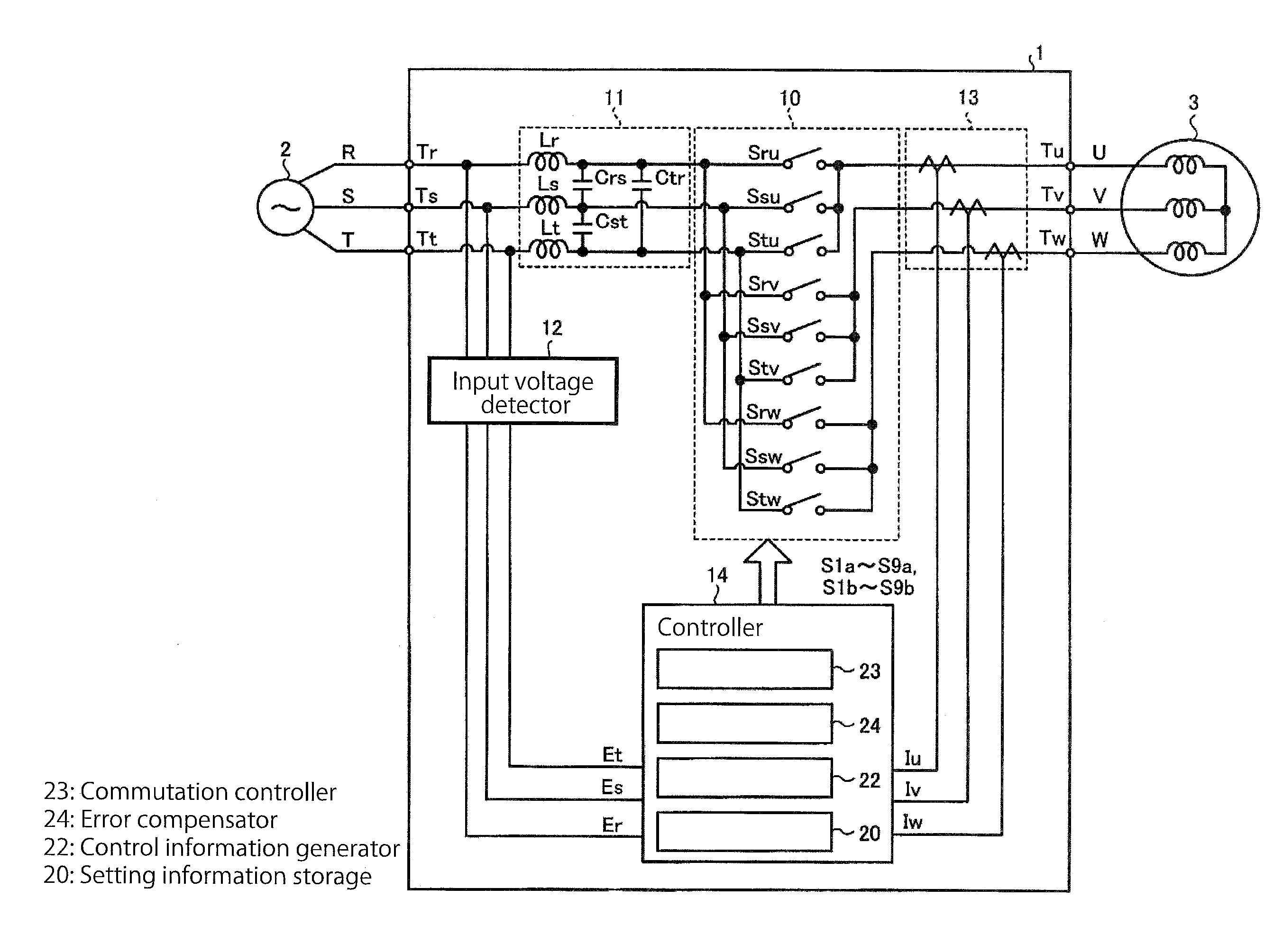
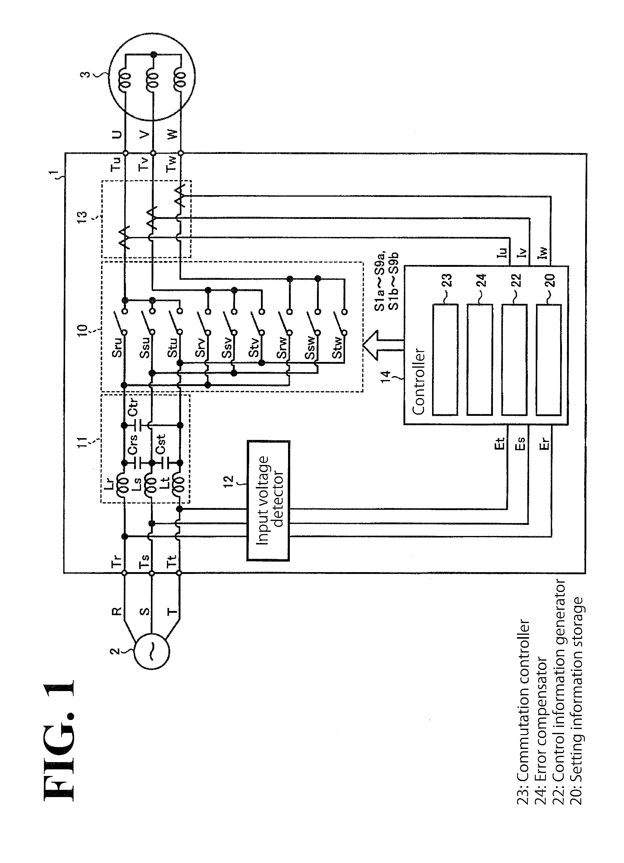
[0032]FIG. 1 illustrates an exemplary configuration of a matrix converter according to an embodiment. As illustrated in FIG. 1, the matrix converter 1 according to this embodiment is disposed between a three-phase AC power supply 2 (hereinafter simply referred to as an AC power supply 2) and a load 3. Examples of the load 3 include, but are not limited to, an AC motor and an electric generator. The AC power supply 2 includes an R phase, an S phase, and a T phase. The load 3 includes a U phase, a V phase, and a W phase. In the following description, the R phase, the S phase, and the T phase will be referred to as input phases, while the U phase, the V phase, and the W phase will be referred to as output phases.

[0033]...


PUM


Abstract

A matrix converter includes a power converter, a control information generator, a commutation controller, a storage, and an error compensator. The power converter includes bidirectional switches each having a conducting direction controllable by switching elements. The bidirectional switches are disposed between input terminals and output terminals. The input terminals are respectively coupled to phases of an AC power source. The output terminals are respectively coupled to phases of a load. The control information generator generates control information to control the bidirectional switches. The commutation controller controls each of the switching elements based on the control information so as to perform commutation control. The storage stores setting information of at least one of a method of the commutation control and a modulation method of power conversion. The error compensator compensates for an output voltage error based on the setting information.

Description

CROSS-REFERENCE TO RELATED APPLICATIONS[0001]The present application claims priority under 35 U.S.C. §119 to Japanese Patent Application No. 2013-236070, filed Nov. 14, 2013. The contents of this application are incorporated herein by reference in their entirety.BACKGROUND[0002]1. Field of the Invention[0003]The present invention relates to a matrix converter and a method for compensating for an output voltage error.[0004]2. Discussion of the Background[0005]Matrix converters each include a plurality of bidirectional switches. The bidirectional switches couple the phases of an AC (Alternating Current) power supply to respective phases of a load. Each matrix converter controls the bidirectional switches to directly switch between the voltages for the phases of the AC power supply so as to output a desired voltage and a desired frequency to the load.[0006]The bidirectional switches each include a plurality of switching elements. When the matrix converter uses the bidirectional switche...

Claims


Application Information

Patent Timeline
Patent Type & Authority Applications(United States)
IPC IPC(8): H02M5/293H02M1/088
CPCH02M5/293H02M2001/0003H02M2005/2932H02M1/088H02M5/297H02M5/2932H02M1/0025H02M1/385H02M1/0003
Inventor YAMAZAKI, AKIRAEBISU, JOJI
Owner YASKAWA DENKI KK
Why Eureka
Try Eureka